background image


ADVANCED MEASUREMENT 


99


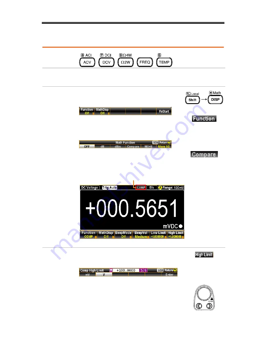
Compare Mode 


Applicable to 


Background 

The Compare mode checks and updates if  measurement data 

stays between the specified upper (high) and lower (low) limit. 

Activate 
Compare 
mode 

Press the Shift + Math key to activate Math 

setting menu as the following figure shown. 


Further press the F1 (Function) key to enter 
the Math Function menu as the figure 

shown below. 


Press F4 (Compare) key to enable the 

Compare function. The screen, after 

activation, will appear as figure below. 


Indicator Compare On


F6 (High 
Limit) to set 
high limit 

Press the F6 (High Limit) key to enter the 
setting menu. 


First use the functions keys to determine the 
unit, which varies by different measure 

modes. Then use the Left/Right arrow keys 

to move cursor and scroll the Knob key or 

press Number Keys to enter the desired 
value of  high limit.   


Summary of Contents for DM2571

Page 1: ...NF Corporation DIGITAL MULTIMETER DM2571 USER MANUAL ...

Page 2: ......

Page 3: ...DA00078064 002 DIGITAL MULTIMETER DM2571 USER MANUAL ISO 9001 CERTIFIED MANUFACTURER ...

Page 4: ...y be photocopied reproduced or translated to another language without prior written consent of NF Corporation The information in this manual was correct at the time of printing However NF continues to improve products and reserves the right to change specifications equipment and maintenance procedures at any time without notice ...

Page 5: ...rement 34 2W 4W Resistance Measurement 38 Continuity Test 41 Diode Measurement 44 Frequency Period Measurement 45 Capacitance Measurement 50 Temperature Measurement 53 DUAL MEASUREMENT 63 Dual Measurement 64 ADVANCED MEASUREMENT 73 Advanced Measurement Overview 74 Relative Value Measurement 75 Hold Measurement 77 Trigger Setting 80 Filter Setting 86 Math Measurement 89 DIGITAL I O 113 Digital I O ...

Page 6: ...re Display 153 SCREENSHOT LOG 173 Capture 174 Save Reading 177 DISPLAY SETTING 181 Digit 182 Display 184 REMOTE CONTROL 203 Configure Interface 204 Web Control Interface 236 Command Syntax 241 Command Set 244 Status system 330 APPENDIX 334 Fuse Replacement 335 Factory Default Parameters 338 Specifications 342 EMC and Safety 357 ...

Page 7: ...ING Warning This contains information to avoid risks in equipment handling that could result in loss of life or bodily injury CAUTION Caution This contains information to avoid risks in equipment handling that could result in minor or moderate injury to person or damage to property or the equipment DANGER High Voltage Attention Refer to the Manual Protective Conductor Terminal Earth ground Termina...

Page 8: ...e personnel Make sure that the Sense LO terminal to Input LO is limited to 2Vpk the Sense HI to Sense LO terminals are limited to 200Vpk and the Input LO to earth is limited to 500Vpk Note EN61010 2 030 2010 specifies the measurement categories and their requirements as follows The DM2571 falls under category II 300V Measurement category IV is for measurement performed at the source of low voltage...

Page 9: ...lace the fuse only with the specified type and rating Disconnect the power cord before fuse replacement Make sure the cause of a fuse blowout is fixed before fuse replacement Cleaning the Instrument Disconnect the power cord before cleaning Use a soft cloth dampened in a solution of mild detergent and water Do not spray any liquid into the product Do not use chemicals or cleaners containing harsh ...

Page 10: ...sed by condensation must be expected Pollution degree 3 Conductive pollution occurs or dry non conductive pollution occurs which becomes conductive due to condensation which is expected In such conditions equipment is normally protected against exposure to direct sunlight precipitation and full wind pressure but neither temperature nor humidity is controlled Storage Environment Location Indoor Tem...

Page 11: ...1 Please note the information in this manual was correct at the time of printing However as NF continues to improve its products changes can occur at any time without notice Please see the NF website for the latest information and content Characteristics 8 Accessories 9 Front Panel Overview 10 Measurement Keys basic 12 Measurement Keys advanced 14 Rear Panel Overview 15 Status Bar 18 Set Up 21 Hor...

Page 12: ...Readings sec Internal memory 100k read memory Data Logging to USB Features 6 2 1 digits Multi functions ACV DCV ACI DCI 2W 4W R Hz Temp Continuity Diode Period Capacitance test REL dBm Hold MX B 1 X REF dB Compare and Statistics Manual or Auto ranging AC true RMS Built in DC Ratio function Up to 3 temerature measurements RTD Thermistor and Thermocouples Cold Junction Compensation Graph Display Bar...

Page 13: ...ssories Part number Description PA 001 3393 GPIB Card PA 001 3395 RS 232C Cable PA 001 3394 4W TEST LEAD CAUTION The power cord set supplied with this equipment is designed to be used for this equipment only Do not use this power cord set for other equipment or purposes Use only the attached power cord set for connection to AC power line ...

Page 14: ... Print screen Data log Key 3 USB Host Port 4 Power Switch 5 Main Display 6 Function keys F1 through F6 functions vary per modes 7 Knob key 8 Arrow Keys 9 Measurement Keys 0 Range Selection Keys A HI and LO Sense Terminals B HI and LO Input Terminals C AC DC Current Input Terminals D Front Rear Input Switch ...

Page 15: ...ns On or Off the main power For the power up sequence see page 22 Main Display The 4 3 TFT LCD shows measurement results and parameters For display configurations see page 153 Measurement Keys There are 4 rows in total of both basic and advanced measurement keys deployed on the front panel For the details refer to page 12 and page 14 Function Keys The 6 keys have varied functions per different set...

Page 16: ...he sense line in 4W Resistance page 38 The maximum withstand voltage between this terminal and earth is 500Vpk Input HI Terminal Used as an input port for all measurements except for DC AC Current measurements DC AC 10A Terminal Accepts DC AC Current input For DCI or ACI details see page 34 Measurement Keys basic Background The upper 2 rows of measurement keys are used for basic measurements such ...

Page 17: ...ration page 204 ACV Measures AC Voltage page 27 Shift ACV ACI Measures AC Current page 34 DCV Measures DC Voltage page 27 Shift DCV DCI Measures DC Current page 34 Ω2W Resistance Measures 2 wire Resistance page 38 Shift Ω2W Ω4W Resistance Measures 4 wire Resistance page 38 Continuity Tests Continuity page 41 Shift Diode Tests Diode page 44 FREQ Frequency Measures Frequency page 45 Shift FREQ Capac...

Page 18: ...elative value measurement page 75 Hold Activates the Hold function page 77 Shift Hold Hold Manually sets the parameters for the Hold measurement page 77 TRIG Trigger Activates the Trigger function page 80 Shift TRIG TRIG Manually sets the parameters for the Trigger function page 80 Menu Enters the setting pages in various Menus page 138 Shift Menu Filter Manually sets the parameters for the Filter...

Page 19: ... 2 HI and LO Input Terminals 3 3 A Current Terminal 4 3 A Current Terminal Fuse 5 DIGITAL I O Connector 6 RS 232 Interface Connector 7 USB Interface Connector B Type 8 Ethernet LAN Connector 9 Fan Vents 0 AC Mains Input Power Cord Socket A AC Mains Line Voltage Selector and Fuse Socket B GPIB Connector optional ...

Page 20: ...remote control DB 9 male connector For remote control details see page 208 USB device port Accepts a USB device cable for remote control Type B female connector For remote control details see page 205 LAN port Accepts a LAN for remote control For remote control details see page 220 Digital I O port Accepts a digital I O cable for the Hi Lo limit tests DB 9 pin female connector For digital I O deta...

Page 21: ... Terminal Accepts ground COM line in all measurements except the sense line in 4W Resistance page 38 The maximum withstand voltage between this terminal and earth is 500Vpk Input HI Terminal Used as an input port for all measurements except for DC AC Current measurements DC AC 3A Terminal DC AC current input DC 100μA to 3A AC 100μA to 3A For details see page 34 DC AC 3 15A Input Current Fuse Holds...

Page 22: ...e control icon 2 RS 232 USB CDC USB TMC LAN GPIB interface icon 3 Error icon for commands from remote control 4 Rear panel switch icon 5 Shift key identification icon 6 The first and second function menu switch icon 7 Digital I O mode icon User 4094 8 USB flash drive connection icon 9 Beep Key Sound setting icon 0 Internet connection status icon A Time display ...

Page 23: ... interface is activated Refer to page 216 for details ERROR It indicates error occurs in commands To erase the error icon it is required to read or sweep the error by remote control commands or reboot action Refer to page 315 for details Rear Panel It indicates rear panel control When the icon appears only rear panel is available otherwise use front panel for measurement Refer to page 15 for detai...

Page 24: ...g It indicates the Save Reading mode is ready for the connected flash drive Refer to page 177 for details of Save Reading Flash Drive Failure It indicates something error occurs and thus flash drive fails to connect to unit Sound Beep It indicates sound of beep is enabled Refer to page 138 for details Sound Key It indicates sound of key is enabled Refer to page 139 for details Sound All It indicat...

Page 25: ...pplications Pull out the handle sideways and rotate it clockwise for the applications below Horizontal Tilt Place the unit horizontally Rotate the handle for tilt stand Vertical Place the handle vertically for hand carry CAUTION Do not use in this state ...

Page 26: ... cord to the AC Voltage input Note Make sure the ground connector on the power cord is connected to a safety ground This will affect the measurement accuracy 3 Push the power button until click to turn on the main power switch on the front panel 4 The screen firstly shows the logo brand of NF Corporation followed by the message Load the Parameter Default is Ok indicating default parameter is loade...

Page 27: ...urement 38 Select Resistance Range 39 General Resistance Setting 40 Continuity Test 41 Set Continuity Threshold 42 Diode Measurement 44 Frequency Period Measurement 45 Frequency Period In Depth Setting 48 Capacitance Measurement 50 Cable Open Function 51 Select Capacitance Range 52 Temperature Measurement 53 General Temperature Setting 54 Thermocouple Sensor Type 55 Reference Junction Temperature ...

Page 28: ...he operation using the result obtained from one or more of the basic measurements Refresh Rate Background Refresh rate defines how frequently the DM2571 captures and updates measurement data A faster refresh rate yields a lower accuracy and resolution A slower refresh rate yields a higher accuracy and resolution Consider these tradeoffs when selecting the refresh rate Measurement Type Refresh Rate...

Page 29: ...ption on screen display Also the F6 More key shows when available options are more than single page The refresh rate will be shown at the upper right corner of the display See the example below Active Refresh Rate Note The refresh rate cannot be set for capacitance measurement Reading indicator The reading indicator which is located in the lower right corner of display flashes according to the def...

Page 30: ... trigger once per click Single Trigger Simply press the TRIG key to Single trigger measurement Pressing once stands for trigger for single time See the figure below for example Indicator Single Trigger Mode Automatic Internal Trigger Press and hold the TRIG key for 2 seconds to return to the Automatic Internal Trigger Indicator Auto Internal Trigger Mode Press hold for 2 seconds Note Single trigge...

Page 31: ...witch to ACV DCV mode immediately See the figure below for example DC or AC Voltage Indicates DC or AC Voltage mode 5 s Indicates the active refresh rate Indicates Automatic range selection Range 100mV Indicates the available range of Voltage 000 1066 mVDC Indicates the exact measured value Connect the test lead and measure Connect the test lead between the Input HI and Input LO terminals The disp...

Page 32: ...ropriate range is unknown select the highest range You can also press the F1 Range key to select a range for the measurement Press the F1 to F6 key to select a desired range for the voltage measurement Selection list Range Resolution Full scale 100mV 0 1μV 119 9999mV 1V 1 μV 1 199999 V 10V 10 μV 11 99999 V 100V 100 μV 119 9999 V 750V AC 1mV 787 500 V 1000V DC 1mV 1050 000 V Note For more detailed ...

Page 33: ...surements but requires additional time to perform the zero measurement With autozero enabled On the DM2571 internally measures the offset following each measurement It then subtracts that measurement from the preceding reading This prevents offset voltages present on the DM2571 s input circuitry from affecting measurement accuracy With autozero disabled Off the DM2571 measures the offset once and ...

Page 34: ...000 V ranges In most situations 10 MΩ is high enough to not load most circuits but low enough to make readings stable for high impedance circuits It also leads to readings with less noise than the Hi Z option which is included for situations where the 10 MΩ load is significant Vs ideal voltage of DUT Rs input impedance of DUT Ri input impedance of DM2571 either 10M or 10G available Hi Z Deviation ...

Page 35: ...s the following illustration The equation of DCV ratio is like the following mathematical calculation See the above equation from which DC Reference Voltage indicates the measured voltage from the Sense terminals Display DCV Ratio Reading Input Voltage Reading Reference Voltage Reading From the screenshot above for example the INP 00 86308V input voltage is divided by the REF 00 85414V reference v...

Page 36: ...s Waveform Peak to Peak AC True RMS DC Sine PK PK 2 828 1 000 0 000 Rectified Sine full wave PK PK 1 414 0 435 0 900 Rectified Sine half wave PK PK 2 000 0 771 0 636 Square PK PK 2 000 1 000 0 000 Rectified Square PK PK 1 414 0 707 0 707 Rectangular Pulse PK PK X Y 2 000 2K K 2 D D D X Y 2D D X Y Triangle Sawtooth PK PK 3 464 1 000 0 000 ...

Page 37: ...n 3 0 voltage measurement will not result in error due to dynamic range limitations at full scale If the crest factor is more than 3 0 it usually indicates an abnormal waveform as seen from the below table Waveform Shape Crest factor Square wave 1 0 Sine wave 1 414 Triangle sawtooth 1 732 Mixed frequencies 1 414 to 2 0 SCR output 100 to 10 1 414 to 3 0 White noise 3 0 to 4 0 AC Coupled pulse train...

Page 38: ...nd DC current Current type AC DC 3A 10A Activate ACI DCI Measure Press the Shift ACV or Shift DCV key to measure AC or DC current respectively or ACI DCI mode display appears The measurement will switch to ACI DCI mode immediately See the figure below for example AC or DC Current Indicates DC or AC Current mode 5 s Indicates the active refresh rate Indicates Automatic range selection Range 100mA I...

Page 39: ...nect the test lead between the 3A terminal and the Input LO terminal or DC AC 10A terminal and the Input LO terminal depending on the input current The display updates the reading For current 3A use the 3 15A terminal For current up to 12A use the 10A terminal ...

Page 40: ...allowed on 10A Manual range Press the or the key to select the range The AUTO indicator turns to indicating Manual range selection If the appropriate range is unknown select the highest range You can also press F1 Range key to select a range for the measurement Press the F1 to F5 key to select a desired range for the measurement Press the F6 More 1 2 key for next page with more options as the figu...

Page 41: ...rements but requires additional time to perform the zero measurement With autozero enabled On the DM2571 internally measures the offset following each measurement It then subtracts that measurement from the preceding reading This prevents offset voltages present on the DM2571 s input circuitry from affecting measurement accuracy With autozero disabled Off the DM2571 measures the offset once and su...

Page 42: ...stances smaller than 1kΩ Activate 2W or 4W Measurement Press the Ω2W key to activate 2W resistance measurement Press the Shift Ω2W key to activate 4W resistance measurement 2W 4W resistance mode display appears The mode will switch to the selected resistance mode immediately Press the Shift Ω2W key on the front panel as figure shown below 2 or 4 Wire OHM Indicates 2W or 4W Resistance mode 5 s Indi...

Page 43: ...rn the automatic range selection On Off press the Auto key Manual range Press the or the key to select the range The Auto indicator turns to indicating Manual range selection If the appropriate range is unknown select the highest range You can also press the F1 Range key to select a range for the measurement Press the F1 to F5 key to select a desired range for the measurement Press the F6 More 1 2...

Page 44: ...ro provides the most accurate measurements but requires additional time to perform the zero measurement With autozero enabled On the DM2571 internally measures the offset following each measurement It then subtracts that measurement from the preceding reading This prevents offset voltages present on the DM2571 s input circuitry from affecting measurement accuracy With autozero disabled Off the DM2...

Page 45: ...ately Press on the front panel as figure shown below Continuity Indicates Continuity measurement 60 s Indicates the active refresh rate Indicates Manual range selection 1kΩ Indicates the available range of Continuity Note the range selection is fixed in 1kΩ OPEN Ω Indicates the currently measured result Connect the test lead and measure Connect the test lead between the Input HI terminal and the L...

Page 46: ...affecting measurement accuracy With autozero disabled Off the DM2571 measures the offset once and subtracts the offset from all subsequent measurements Display When turning On the Auto Zero the display shows an icon indicating the Auto Zero mode is currently being activated F4 BeepVol key to select the Vol Press the F2 to F4 key to select the volume level or press the F1 key to set Beep volume off...

Page 47: ...ity menu as the figure below shown Set the continuity threshold level 1 Use the Left Right arrow keys to move cursor and scroll the Knob key or press Number keys to enter the desired value 2 Press the F6 Enter key or the Knob key until click to confirm the threshold settings Display ...

Page 48: ...de mode immediately as the figure shown below Diode Indicates the Diode measurement 60 s Indicates the active refresh rate Indicates Manual range selection 5V Indicates the available range of Diode Note the range selection is fixed in 5V 0 449395 VDC Indicates the exact measured value Connect the test lead and measure Connect the test lead between the Input HI terminal and the LO terminal Anode V ...

Page 49: ... DM2571 measures the offset once and subtracts the offset from all subsequent measurements Display When turning On the Auto Zero the display shows an icon indicating the Auto Zero mode is currently being activated Frequency Period Measurement Description The DM2571 can be used to measure the frequency or period of an input signal Range Frequency 3Hz to1MHz Period 1 0μs to333ms Activate frequency o...

Page 50: ...ath Display Frequency Mode Indicator Frequency Mode Period Value in Sub Section Frequency Value Period Mode Indicator Period Mode Frequency Value in Sub Section Period Value Frequency mode display appears The mode will switch to the Frequency or Period mode immediately Press on the front panel followed by clicking F3 key to choose Frequency as shown below Frequency Indicates Frequency measurement ...

Page 51: ... Period value Connection Depending on different inputs connect test lead to varied terminals In terms of voltage connect test leads between the Input HI terminal and the LO terminal The display updates the reading In terms of current connect test leads between the 3A terminal and the LO terminal or DC AC 10A terminal and the LO terminal The display updates the reading ...

Page 52: ...e F2 key to enter gate time menu Click the F1 F3 key for the desired gate time See the figure below with available options F4 InJack key to select voltage or current Background In accordance with the target inputs choose the corresponding selection per condition E g select 3A when the input current is below 3A amplitude Press the F4 InJack key to determine whether the voltage or current 3A or curr...

Page 53: ...al range selection If the appropriate range is unknown select the highest range You can also press the F1 AC Range key to select a range for the measurement Depending on the InJack setting the available options vary See examples below When InJack is Voltage Press the F1 to F6 key to select a desired range for the measurement When InJack is 3A Press the F1 to F5 key to select a desired range for th...

Page 54: ...immediately Press on the front panel as shown below Capacitance Indicates the Capacitance measurement 2 s Indicates the active refresh rate Note refresh rate of Capacitance is fixed in 2 s Indicates Automatic range selection Range 100nF Indicates the available range of Capacitance 105 0 nF Indicates the exact measured value Connect the test lead and measure Connect the test lead between the Input ...

Page 55: ...ing capacity in small scale Display Range 1nF or 10nF Cable Open F3 Activate cable open function Connect test leads followed by pressing the F3 Cable Open key to proceed to Cable Open function The measured value will be rectified and returned to zero as the figure shown below Connect the test lead and measure Follow the connection method of capacitance measurement to measure and obtain precise pro...

Page 56: ...1 Range key to select a range for the measurement Press the F1 to F5 key to select a desired range for the measurement Press the F6 More 1 2 key for next page with more options as the figure shown below Selectable Capacitance Ranges Range Resolution Full scale 1nF 1pF 1 199nF 10nF 10pF 11 99nF 100nF 100pF 119 9nF 1μF 1nF 1 199μF 10μF 10nF 11 99μF 100μF 100nF 119 9μF Note For further details please...

Page 57: ...ure Range Thermocouple 200 C to 1820 C vary by sensor types RTD 200 C to 630 C Thermistor 80 C to 150 C Activate temperature measurement Press the TEMP key to activate temperature measurement Temperature mode display appears Temperature Indicates Temperature measurement 0214 552 C Indicates the exact measured value T Couple Indicates the active Probe Type R Indicates the active Type Connect the te...

Page 58: ...tracts that measurement from the preceding reading This prevents offset voltages present on the DM2571 s input circuitry from affecting measurement accuracy With autozero disabled Off the DM2571 measures the offset once and subtracts the offset from all subsequent measurements Display When turning On the Auto Zero the display shows an icon indicating the Auto Zero mode is currently being activated...

Page 59: ... 50 to 1768 C 0 01 C T 200 to 400 C 0 002 C B 350 to 1820 C 0 01 C E 200 to 1000 C 0 002 C Reference Junction Temperature SIM Temperature Background Thermocouple only When a thermocouple is connected to the DM2571 the temperature difference between the thermocouple lead and the DM2571 input terminal should be taken into account and be cancelled out otherwise an erroneous temperature might be added...

Page 60: ...ing to the previous menu page You can select either the default fixed 23 00 or the Auto option for the so called Reference Junction Temperature as following When selecting 23 00 by F1 23 00 key the display shows an icon indicating the simulated baseline is 23 C If choosing Auto by F2 Auto key the subset menu appears with additional option Press the F3 ADJ 00 00 key followed by inputting a desired ...

Page 61: ...e Temperature Probe menu followed by clicking either the F2 RTD 2W or F3 RTD 4W key to activate RTD 2W 4W mode See the figure shown below 2 Press the F5 Type key to enter the Sensor Type menu as the figure shown below Click the F1 F5 key to select a desired sensor type per your requirement 3 The display shows the latest setting See the example of the figure below where RTD 2W PT100 is currently ac...

Page 62: ...dividually as defined by the Callendar Van Dusen equation Type Coefficient Alpha α Beta β Delta δ PT100 0 00385 0 10863 1 49990 D100 0 00392 0 10630 1 49710 F100 0 00390 0 11000 1 49589 PT385 0 00385 0 11100 1 50700 PT3916 0 00392 0 11600 1 50594 Equation 200 C to 0 C range 0 C to 630 C range Operate Procedure 1 Press the F5 Type key to enter the Sensor Type menu followed by pressing the F6 User k...

Page 63: ...ter the desired value α default 0 00385 α range 0 to 9 999999 4 Press the F6 Enter key or the Knob key to confirm the input α value and repeat the previous steps 2 4 to set up the β Beta δ Delta and R0 coefficients individually β default 00 10863 δ default 1 49990 R0 default 100 β δ range 0 to 9 999999 R0 range 80 to 120 RTD Beta Setup RTD Delta Setup RTD R0 Setup 5 After returning to the User Typ...

Page 64: ...emperature Probe menu followed by clicking either the F4 Therm2W or F5 Therm4W key to activate Therm 2W 4W mode See the figure shown below 2 Press the F5 Type key to enter the Sensor Type menu as the figure shown below Click the F1 F3 key to select a desired sensor type per your requirement 3 The display shows the latest setting See the example of the figure below where Thermistor 2W 10kΩ is curre...

Page 65: ...02356 9 56E 08 10k 0 0010295 0 0002391 1 57E 07 Equation Operate Procedure 1 Press the F5 Type key to enter the Sensor Type menu followed by pressing the F4 User key to activate User Type 2 Press the F6 User Type key to enter the User Type Setup menu where A B and C coefficients can be set up respectively Click the F1 A 1 2880E 03 key to enter the THERM A Setup page as the figure shown below Use t...

Page 66: ... 2 4 to set up the B and C coefficients individually B range 0 to 9 9999 default 2 35600E 04 C range 0 to 9 9999 default 9 55700E 08 THERM B Setup THERM C Setup 4 After returning to the User Type Setup page if necessary press the F6 5 kΩ DEF key to restore to the default coefficients setting based on the 5 kΩ sensor type ...

Page 67: ...DUAL MEASUREMENT 63 DUAL MEASUREMENT Dual Measurement 64 Refresh Rate 67 Connect the Test Leads 68 The error influence on Dual Measurement V I 71 ...

Page 68: ...n for both displays such as ACV and frequency period measurements If the primary and secondary displays use different measurement functions ranges or rates then separate measurements will be taken for each display For example ACV and DCV measurements Most of the basic measurement functions except for resistance continuity diode capacitance can be used in the dual measurement mode The following tab...

Page 69: ...isplay 1ST Display Shows the DCV measurement 2ND Display Shows the ACV measurement in orange Indicates that 1ST display is the currently active display Editing 1st or 2nd measurement item settings After the secondary measurement function has been activated the rate range and measurement item can be edited for either the primary or secondary display Note however it is more practical to configure th...

Page 70: ...Display 1ST in active display 2ND in active display 2 Edit active display settings Edit the range rate or measurement item for the active display in the same way as for single measurement operation See the Basic Measurement on page 23 for details Turn Off 2nd Measurement To turn Off the 2ND measurement first toggle in 1ST active display followed by pressing the F6 2ND key Click the F6 OFF key agai...

Page 71: ... 2 4k s 4 8k s 7 2k s 10k s ACV ACI 1 s 5 s 50 s Frequency Period 1s 100ms 10ms Selection steps 1 Toggle the active display between the 1ST and 2ND display by pressing the Knob key until click 2 Press the F2 Speed key to select a desired rate for measurement Press the corresponding function key F1 F5 in accord with the desired option on screen display Also press the F6 More 1 2 key to enter the ne...

Page 72: ... display Reading Indicator Connect the Test Leads Connect the test leads and measure When using the dual measurement function the connection method and number of test leads required depends on the measurement combination Use the connect diagrams below as guide when taking dual measurements Voltage and Frequency Period Measurement ...

Page 73: ...ies with the test circuit The above measuring configuration is used to measure the voltage present on the resistance under test and the current through the resistance under test when using the DCI DCV or ACI ACV dual measurement function When dual measurement DCI DCV or ACI ACV is underway the input impedance will change thus resulting in load deviation due to the fluctuation of different measurin...

Page 74: ...DM2571 User Manual 70 DC Current and Temperature Measurement Sense HI LO connects to K Type whilst Input 3A LO connects DCI source ...

Page 75: ...ltage reading will be influenced Diagram Fuse Rshunt Rline 3A Rline HI LO DMM INPUT Example Vs Voltage source RLoad Load under test Rint Current terminal total impedance containing Rshunt Fuse Rline Rline Rline Rline When different current range for measurement is selected Rshunt will vary accordingly For example Vs 10V Rload 10 Ω Vs 10V Rload 10 Ω If the total impedance passing through current te...

Page 76: ...DM2571 User Manual 72 ...

Page 77: ...Hold Measurement 77 Trigger Setting 80 Automatic Single Triggering 80 Use External Trigger 81 Set Trigger Delay 84 Filter Setting 86 Digital Filter Overview 86 Digital Filter Setting 87 Math Measurement 89 dBm dB Watt Measurement 89 Compare Mode 99 MX B Measurement 105 1 X Measurement 108 Measure Percent 110 ...

Page 78: ...ers to the type of measurement which uses the result obtained by one of the basic measurements ACV DCV ACI DCI 2 4W Diode Continuity Frequency Period and Temperature Advanced Measurement Basic Measurement AC DC V AC DCI 2 4W Hz P TEMP Relative Hold Trigger Filter dB dBm Compare MX B 1 X Percent ...

Page 79: ...g impedance measurement short circuit the test lead followed by pressing the REL button For other measurements press the REL button after putting test lead in a null circuit Alternatively user can modify the value by pressing the REL button followed by using the knob or number keys to enter a specified value Press the REL button again to disable null operation Activate Relative measurement Press t...

Page 80: ...tion keys to decide unit value Then use the Left Right arrow keys to move cursor and scroll the Knob key or press Number keys to enter the desired value Press the F6 Enter key or the Knob key until click to confirm the relative value setting or Deactivate Relative measurement To cancel the Relative measurement press the REL key again or simply activate another measurement ...

Page 81: ... Measurement The Latest Hold Value Hold Indicates Hold measurement 000 6801 mVDC Shows the latest hold value Enter hold settings Press the Shift Hold key to activate detailed setting menu of Hold mode as the figure below F5 Percent key to define threshold Press the F5 Percent key to show the setting menu of Hold Percent as the figure below Press F1 to F4 key to select desired hold percent For exam...

Page 82: ...h display in accord with the following chapters Show STAT result Background The STAT page in MathDisp allows you to make statistical calculations for several measurements including Minimum Maximum Average Peak Peak Standard Deviation and Count Operation Press the F2 STAT key to show the statistical data immediately as the figure below View Data 000 9716 mVDC Indicates the latest hold value Minimum...

Page 83: ...tion Press the F3 Math key to show the mathematical analysis instantly as below View Data 000 7098 mVDC Indicates the latest hold value Measure 000 7326mV Indicates the originally measured mV value 5 hold values in blue Indicates the latest 5 counts of hold values F6 HoldValue key to restart Press the F6 HoldValue key to simply Restart the hold value ...

Page 84: ...ault the DM2571 triggers according to the refresh rate automatically See the previous page for refresh rate setting details The figure below shows the screen of Automatic Trigger measurement Auto Trigger Mode Single triggering Press the TRIG key to Single trigger measurement See below for details Single Trigger Mode ...

Page 85: ...he TRIG button to return to Single Trigger mode Use External Trigger Background The DM2571 uses the internal trigger by default for example to count the frequency and the period Using an external trigger allows customized triggering conditions Signal connection Connect the external trigger signal to the Digital I O port located on the rear panel DB 9 female Digital I O pin assignment ...

Page 86: ...ress the F2 SampCount key to enter the ensuing setting of Sample Count Use the Left Right arrow keys to move cursor and scroll the Knob key or press Number keys to enter the desired counts 2 Push the Knob key Enter or press the F6 Enter key to confirm the input value Range 1 to 1 000 000 or Set Trigger Signal Background When utilizing external trigger select either positive or negative terminal as...

Page 87: ...ator The reading indicator does not flash before triggering can be on or off After triggering the indicator flashes according to the external signal trigger timing Exit external trigger Press the F1 TrigSource key to reenter the TrigSource menu followed by pressing the F1 Auto or the F2 Single key to switch to other trigger modes Alternatively it is viable to simply click the TRIG button to change...

Page 88: ...Delay 1ST menu The Trigger Delay setting appears as the figure below Note the F4 2ND Delay key is only available when 2ND measurement is activated 3 Press the F4 AutoDelay key to switch to the manual delay time setting 4 Use F1 F3 keys to decide unit value Then use the Left Right arrow keys to move cursor and scroll the Knob key or press Number keys to enter the desired value 5 Push the Knob key E...

Page 89: ... 1 2 of manual trigger delay first and press the F4 AutoDelay key to switch the display as the following 2 Press the ESC key to return to the previous page and have the auto trigger delay setting take effect The 1ST display will be shown like the following figure ...

Page 90: ...ollowing diagrams highlight the differences between the Moving and Repeating filter using 4 samples per reading Moving default The Moving filter takes in one new sample and discards the oldest sample per reading This is the default behavior when the digital filter is not specified and is recommended for most applications 1 Sample 1st reading Sample 1 4 2nd reading Sample 2 5 3 2 4 5 6 7 8 9 10 11 ...

Page 91: ...of the range between TH and TL the filter will restart When measuring unstable signals appropriately setting the filter window can improve the measurement speed Time AD data TH TL TH TL TH TL Filter Filter Filter Restart Restart TH Threshold High TL Threshold Low Filter window Formula Measure Previous Meas 1 window threshold Previous Meas 1 window Range Previous Measure Range window threshold Prev...

Page 92: ...l be disabled Choose filter type Press the F3 FilterType key to enter the subsequent menu Press the F1 or F2 keys to select desired filter type Define filter count Press the F4 FilterCount key to enter the subsequent menu Use the Left Right arrow keys to move cursor and scroll Knob key or press Number keys to enter the desired value Press the F6 Enter key or the Knob key until click to confirm the...

Page 93: ...surement Applicable to Background Math measurement runs 6 types of mathematical operations dBm dB Compare MX B 1 X and Percent based on the other measurement results Math Equation dBm 10 x log10 1000 x Vreading2 Rref dB dBm dBmref Compare Checks and updates if measurement data stays between the specified upper high and lower low limit MX B Multiplies the reading X by the factor M and adds subtract...

Page 94: ...ing an output load dBmref Reference dBm value Measure dBm Watt Applicable to Equation dBm 10 x log10 1000 x Vreading2 Rref Watt Vreading2 Rref Parameters Vreading Input Voltage ACV or DCV Rref REF Ω Reference resistance simulating an output load Activate dBm Press the Shift key Math key to activate Math setting menu as the following figure shown Further press the F1 Function key to enter the Math ...

Page 95: ...ce Push the Knob key Enter or press the F6 Enter key to confirm the input reference resistance or Resistance List 2 4 8 16 50 75 93 110 124 125 135 150 250 300 500 600 800 900 1000 1200 8000 View result in Watt When the reference resistance is less than 50Ω it is possible to calculate the watt value If the reference resistance is greater than 50Ω please ignore this step To calculate the Watt power...

Page 96: ...esult Background The STAT page in MathDisp allows you to make statistical calculations for several measurements including Minimum Maximum Average Peak Peak Standard Deviation and Count Operation Press the F2 STAT key to show the statistical data immediately as the figure below View Data 00 00000 W Indicates the latest W value Minimum Indicates the minimum data value Maximum Indicates the maximum d...

Page 97: ...o show the mathematical analysis instantly as below View Data 00 00000 dBW Indicates the latest dBW value Measure 000 0006V Indicates the originally measured Voltage value RefΩ Indicates the defined reference Ω value Deactivate dBm dBW measurement To cancel the dBm dBW measurement press the F1 Function key followed by clicking F1 OFF key to deactivate or simply activate another measurement Measure...

Page 98: ...unction key to enter the Math Function menu as the figure shown below Press F2 dB key to enable the dB function The screen after activation will appear as figure below dB result appears Measured dB Value Indicator dB On F3 REF Ω to select reference resistance To change the reference resistance press the F3 REF Ω key to enter the setting menu Scroll the Knob key or press Number keys to enter the de...

Page 99: ...ess the F4 RefMethod key to enter the dB Ref Method menu followed by clicking the F1 Voltage or F2 dBm key to determine which method of calculation to proceed to F5 Ref Value to define reference value voltage or dBm In order to define either voltage or dBm reference value both of which are corresponding to the previous F4 Ref Method option press the F5 Ref Value to enter the dB Ref Value menu and ...

Page 100: ... make the current dBm value which is calculated by the current input voltage with the equation as the Ref dBm dBm reference F2 MathDisp key to show STAT Math Press the F2 MathDisp key to show the option menu as the figure below shown Proceed to the F2 STAT or F3 Math display in accord with the following chapters ...

Page 101: ...nd Count Operation Press the F2 STAT key to show the statistical data immediately as the figure below View Data 10 28281 dB Indicates the calculated dB value Minimum Indicates the minimum data value Maximum Indicates the maximum data value Average Indicates the mean average value Peak Peak Indicates the peak to peak data STDEV Indicates the standard deviation of the data Count Indicates the latest...

Page 102: ...dicates the calculated dB value Measure 000 7479mV Indicates the originally measured m Voltage value Ref Ω 0002 Ω Indicates the defined reference resistance value Ref Voltage 003 0330mV Indicates the measured reference voltage value Ref dBm 023 3727 Indicates the measured reference dBm value Deactivate dB measurement To cancel the dB measurement press the F1 Function key followed by clicking F1 OF...

Page 103: ...ction key to enter the Math Function menu as the figure shown below Press F4 Compare key to enable the Compare function The screen after activation will appear as figure below Indicator Compare On F6 High Limit to set high limit Press the F6 High Limit key to enter the setting menu First use the functions keys to determine the unit which varies by different measure modes Then use the Left Right ar...

Page 104: ...it Push the F6 Enter key or the Knob key Enter to make the setting into effect or F3 BeepMode to define beep mode Press the F3 BeepMode key to enter the beep mode setting By enabling beep mode user can be aware of the latest state promptly by beep voice The display shows as the figure below Press the F2 Pass or F3 Fail key to determine the condition of beep alarm Press the F1 Off key to disable be...

Page 105: ...state of Fail See the contents below for more details of each state in compare mode High If the compare result is High the relative pins of digital I O port in action are as the follows Digital I O FAIL Out Pin 6 and HIGH Limit FAIL Out Pin 7 are activated Low If the compare result is Low the relative pins of digital I O port in action are as the follows Digital I O FAIL Out Pin 6 and LOW Limit FA...

Page 106: ...aximum Average Peak Peak Standard Deviation and Count Operation Press the F2 STAT key to show the statistical data as the figure below View Data 000 4835 mVDC Indicates the currently measured mVDC value Minimum Indicates the minimum data value Maximum Indicates the maximum data value Average Indicates the mean average value Peak Peak Indicates the peak to peak data STDEV Indicates the standard dev...

Page 107: ...the defined high limit High Fail Indicates the counts of above the defined high limit Show Math STAT result Background The Math STAT page in MathDisp allows you to view data from both statistical calculations and mathematical analysis Operation Press the F4 Math STAT key to show the hybrid page of Math STAT instantly as figure below View Data 0 001003 VDC Indicates the currently measured mVDC valu...

Page 108: ...e below for the High result in Math STAT mode The boldly red background along with the indicator HIGH within the display means the compare result is over the range of defined high limit Digital I O The Compare measurement result comes out from the rear panel Digital I O terminal For the terminal details see page 113 Deactivate Compare measurement To cancel the Compare measurement press the F1 Func...

Page 109: ... The screen after activation will appear as figure below Indicator MX B On MX B Calculation F3 M Value key to set the factor M Press the F3 M Value key to enter the MX B M Value menu First use function keys to decide unit value which may vary by different measurements Then use the Left Right arrow keys to move cursor and scroll the Knob key or press Number keys to enter the desired value See the f...

Page 110: ... MathDisp key to show the option menu as the figure below shown Proceed to the F2 STAT or F3 Math display in accord with the following chapters Show STAT result Background The STAT page in MathDisp allows you to make statistical calculations for several measurements including Minimum Maximum Average Peak Peak Standard Deviation and Count Operation Press the F2 STAT key to show the statistical data...

Page 111: ...ss the F3 Math key to show the mathematical analysis instantly as below View Data 0 999999 kVDC Indicates the currently MX B calculating result Measure 000 9389mV Indicates the originally measured m Voltage value M Value Indicates the defined M value B Value Indicates the defined B value Deactivate MX B measure To cancel the MX B measurement press the F1 Function key followed by clicking F1 OFF ke...

Page 112: ...sing the F1 1 X key The 1 X function will be activated as the figure below Indicator 1 X On The Measured 1 X Value F2 MathDisp key to show STAT Math Press the F2 MathDisp key to show the Math Display menu as the figure below shown Proceed to the F2 STAT or F3 Math display in accord with the following chapters Show STAT result Background The STAT page in MathDisp allows you to make statistical calc...

Page 113: ...iation of the data Count Indicates the latest counts of 1 X Show Math result Background The Math page in MathDisp allows you to view mathematical calculations for several parameters Operation Press the F3 Math key to show the mathematical analysis as the figure below View Data 02 15782k Indicates the 1 X calculation Measure 000 4634 Indicates the originally measured m Voltage value Deactivate 1 X ...

Page 114: ...the next page followed by pressing the F2 Percent key Percent function will be activated as the following figure shown Indicator Percent On The Measured Percent Value F3 REF key to set reference Press the F3 REF key to enter the Percent REF menu First use the functions keys to determine the unit which may vary by different measure modes Then use the Left Right arrow keys to move cursor and scroll ...

Page 115: ...urements including Minimum Maximum Average Peak Peak Standard Deviation and Count Operation Press the F2 STAT key to show the statistical data immediately as the figure below View Data 040 6525 Indicates the Percent calculation Minimum Indicates the minimum data value Maximum Indicates the maximum data value Average Indicates the mean average value Peak Peak Indicates the peak to peak data STDEV I...

Page 116: ... Indicates the Percent calculation Measure 000 4886mV Indicates the originally measured m Voltage value Ref 000 5908m Indicates the defined reference value Deactivate percent measurement To cancel the percent measurement press the F1 Function key followed by clicking F1 OFF to deactivate or simply activate another measurement ...

Page 117: ...I O Digital I O Overview 114 Application Compare Mode 116 Application 4094 User Mode 123 User Mode IO Output Mode 123 User Mode Switch Mode LED 125 User Mode Switch Mode Relay 127 4094 Mode 129 Application External Trigger 131 ...

Page 118: ... of pins 5 to 8 controlled via remote control By providing separate VCC power for the terminal the outputs can also be used as a power source for TTL and CMOS circuits Related Commands DIGital INTerface MODE DIGital INTerface MODE COMP 4094 IO DIGital INTerface DATA OUTPut For 4094 Mode DIGital INTerface DATA SETup For User Mode Pin Assignment Connector type DB 9 female Pin No Compare Mode 4094 Mo...

Page 119: ... is 100mA Pin2 Flyback Diode Connect to VCC or External power source Pin3 Digital chassis Ground Pin4 External Trigger Input Accepts external trigger signals For using external signals Pins 3 4 output wiring diagram Pin5 8 Pin 5 8 are designed as composite pins which can be specified by user for diversified functions as follows Compare 4094 User Mdoe Refer to the page 116 for details of Compare Mo...

Page 120: ...nal is an active low signal In addition an active low pulse of approximately 2µs is output to indicate the end of compare measurement EOM When the input signal exceeds the high threshold or the low threshold the High Fail or Low Fail pin is pulled low When the signal stays within the threshold levels the Pass pin is pulled low Pin Assignment Pin No Compare Mode Description 1 VCC Out Option Vcc 2 F...

Page 121: ...The screen after activation will appear as figure below Indicator Compare On F6 High Limit to set high limit Press the F6 High Limit key to enter the setting menu First use the functions keys to determine the unit which varies by different measure modes Then use the Left Right arrow keys to move cursor and scroll the Knob key or press Number Keys to enter the desired value of high limit Push the F...

Page 122: ... Enter to make the setting into effect or F3 BeepMode to define beep mode Press the F3 BeepMode key to enter the beep mode setting By enabling beep mode user can be aware of the latest state promptly by beep voice The display shows as the figure below Press the F2 Pass or F3 Fail key to determine the condition of beep alarm Press the F1 Off key to disable beep mode or F4 BeepVol to select beep vol...

Page 123: ... of Fail See the contents below for more details of each state in compare mode High If the compare result is High the relative pins of digital I O port in action are as the follows Digital I O FAIL Out Pin 6 and HIGH Limit FAIL Out Pin 7 are activated Low If the compare result is Low the relative pins of digital I O port in action are as the follows Digital I O FAIL Out Pin 6 and LOW Limit FAIL Ou...

Page 124: ...aximum Average Peak Peak Standard Deviation and Count Operation Press the F2 STAT key to show the statistical data as the figure below View Data 000 4835 mVDC Indicates the currently measured mVDC value Minimum Indicates the minimum data value Maximum Indicates the maximum data value Average Indicates the mean average value Peak Peak Indicates the peak to peak data STDEV Indicates the standard dev...

Page 125: ...f above the defined high limit Show Math STAT result Background The Math STAT page in MathDisp allows you to view data from both statistical calculations and mathematical analysis Operation Press the F4 Math STAT key to show the hybrid page of Math STAT instantly as figure below View Data 0 001003 VDC Indicates the currently measured mVDC value Blue Section It is identical to the contents of STAT ...

Page 126: ...icator HIGH within the display means the compare result is over the range of defined high limit Timing Diagram for pins 5 8 when the Compare function is activated Low limit High limit P P P F F H L Pin 5 PASS Out Pin 6 FAIL Out Pin 7 HIGH Limit FAIL Out Pin 8 LOW Limit FAIL Out Pin 5 8 Output Compare On Deactivate Compare measurement To cancel the Compare measurement press the F1 Function key foll...

Page 127: ...izing output as general IO Output usage with up to 4 pins available for use simultaneously Refer to the following introductions along with diagrams for more details Please see the digital I O commands on page 275 for full usage details Related Commands DIG INT MODE IO switch to IO mode DIG INT DATA SET 0 1 1 0 OUT1 Pin5 0V OUT2 Pin6 5V OUT3 Pin7 5V OUT4 Pin8 0V Pin Assignment Pin No User Mode Desc...

Page 128: ...DM2571 User Manual 124 Pin Diagram Use the built in power supply Note Pin1 and Pin2 Not in use Use in conjunction with the logic gate Note Pin2 Not in use ...

Page 129: ...diagrams for more details Please see the digital I O commands on page 275 for full usage details Related Commands DIG INT MODE IO switch to IO mode DIG INT DATA SET 1 0 0 1 OUT1 Pin5 LED OFF OUT2 Pin6 LED ON OUT3 Pin7 LED ON OUT4 Pin8 LED OFF Pin Assignment Pin No User Mode Description 1 VCC Out Option Vcc 5V 2 Flyback Diode No Use 3 Digital Ground Option GND 5 OUT1 Use 6 OUT2 Use 7 OUT3 Use 8 OUT...

Page 130: ...DM2571 User Manual 126 Pin Diagram Use the built in power supply Note Pin2 and Pin3 Not in use Use the external power Note Pin1 and Pin2 Not in use ...

Page 131: ...or more details Please see the digital I O commands on page 275 for full usage details Related Commands DIG INT MODE IO switch to IO mode DIG INT DATA SET 1 0 1 0 OUT1 Pin5 RELAY OFF OUT2 Pin6 RELAY ON OUT3 Pin7 RELAY OFF OUT4 Pin8 RELAY ON Pin Assignment Pin No User Mode Description 1 VCC Out Option Vcc 5V 2 Flyback Diode Use connect to Pin1 or Ext Vcc 3 Digital Ground GND 5 OUT1 Use 6 OUT2 Use 7...

Page 132: ...r Manual 128 Pin Diagram Use the built in power supply which provides the power of maximum 100mA Note Pin3 Not in use Use the external power 5 to 24V Maximum Ids of each channel 400mA Note Connect Pin2 to Ext Vcc ...

Page 133: ...he digital I O commands on page 275 for full usage details Related Commands DIG INT MODE 4094 switch to 4094 mode 4094 x 1 8 Pin DIG INT DATA OUTP 10 1 4094 Output Out1 to Out8 01010000 4094 x 2 16 Pin DIG INT DATA OUTP 22 0 DIG INT DATA OUTP 88 1 4094 Output Out1 to Out8 01101000 Out9 to Out16 00011010 Note 0 output is Low 0V 1 output is High 5V Pin Assignment Pin No 4094 Mode Description 1 VCC O...

Page 134: ...DM2571 User Manual 130 Pin Diagram Use the built in power supply Note Pin2 Not in use Use the external power Note Pin1 and Pin2 Not in use Method of series Note Pin1 and Pin2 Not in use ...

Page 135: ...71 To trigger the DM2571 a pulse of 10μs is needed The READ command can also be used to externally trigger the DM2571 when the DM2571 is in the external trigger mode See page xxx for details Signal connection Connect the external trigger signal to the Digital I O port located on the rear panel Pin4 External Trigger Input pin Connection ...

Page 136: ...select External Trigger mode The EXT indicator appears on the display External Trigger Mode Reading indicator The reading indicator does not flash before triggering can be on or off After triggering the indicator flashes according to the external signal trigger timing Exit external trigger Press the Shift key followed by the TRIG key The EXT indicator disappears and the trigger goes back to intern...

Page 137: ...SYSTEM FIRMWARE 133 SYSTEM FIRMWARE View System Info 134 Firmware Update 135 ...

Page 138: ...ter Firmware and Slave Firmware Step 1 Press the Menu key the System configuration menu appears And press the NEXT key repeatedly or scroll the Knob key to move to the Security Info SystemInfo field 2 Press the F5 Enter key or Knob key to enter the System Information where all the critical contents are exposed for check ...

Page 139: ...y or scroll the Knob key to move to the Cali Update Firmware field 2 Press the F5 Enter key or Knob key to enter the Firmware Update menu Firmware Update Update Process Prior to update make sure if the required firmware file is stored within the flash drive plugged into the USB port on the front panel Also user can check the current Master and Slave firmware version respectively in this menu ...

Page 140: ... bin Slave file S_IMAGE bin 1 Press the F5 Enter key or Knob key first the qualified firmware version will show then Note If flash drive has no update files it will show as the figure below 2 Press the NEXT key or scroll Knob key to move to the Update followed by pressing the F5 Enter key or Knob key to Start update ...

Page 141: ...Save and Load Setting 143 Firmware Update 148 Security Setting 149 View System Info 152 Configure Display 153 Brightness Setting 153 Auto Off Setting 154 Auto Off Time Setting 155 1ST Color Setting 157 2ND Color Setting 158 Math Color Setting 160 Display Mode Setting 162 Anti Aliasing Setting 167 Additional lnfo Setting 168 Language Setting 170 ...

Page 142: ... Enable or Disable Beep Sound Step 1 Press the Menu key the System configuration menu appears 2 Press the F5 Enter key or Knob key followed by scrolling Knob key or pressing keys to land on the ON option 3 Press the F5 Enter key or Knob key to select the ON option ...

Page 143: ...tem configuration menu appears And then press the NEXT key repeatedly or scroll the Knob key to move to the Key Sound field 2 Press the F5 Enter key or Knob key followed by scrolling Knob key or pressing keys to land on the On option 3 Press the F5 Enter key or Knob key to select the ON option for Key Sound ...

Page 144: ...d press the NEXT key repeatedly or scroll the Knob key to move to the Date Time Date field 2 Use the Left Right keys to move the cursor followed by scrolling Knob key or pressing keys to define year of Date Also you can press Number keys to directly input a specific digit 3 Press the F5 Enter key or Knob key to confirm the input digit for year of Date 4 Repeat steps 2 to 3 for month and day ...

Page 145: ...ss the NEXT key repeatedly or scroll the Knob key to move to the Date Time Time field 2 Use the Left Right keys to move the cursor followed by scrolling Knob key or pressing keys to define hour of Time Also you can press Number keys to directly input a specific digit 3 Press the F5 Enter key or Knob key to confirm the input digit for hour of Time 4 Repeat steps 2 to 3 for minute and second ...

Page 146: ...Menu key the System configuration menu appears And press the NEXT key repeatedly or scroll the Knob key to move to the Date Time TimeSync field 2 Press the F5 Enter key or Knob key to enter the Internet Time Sync menu Internet Time Synchronize Enable Synchronize Enable or disable time sync Check Uncheck Synchronize Server Choose remote server for time sync ...

Page 147: ...Set the time zone Set UTC Coordinated Universal Time hour minute Last Update Time is Display the currently standard time Save and Load Setting Background The DM2571 can save up to 5 instrument settings The settings can save the state function I O and range The Recall function enables saved settings or default settings to be recalled at the next power up or immediately Step 1 Press the Menu key the...

Page 148: ... to enter the Parameter Save Load menu Parameter Save Load Save Select a Group 1 Press the F5 Enter key or Knob key to open the dropdown menu 2 Scroll the Knob key or pressing keys followed by pressing the F5 Enter key or Knob key to confirm the group selection ...

Page 149: ...ard page 2 Press the F2 Backspace key to clear default words 3 Use the Left Right and keys or scroll the Knob key to move the cursor to desired word followed by pressing the F5 Input key or Knob key to input the word 4 Press the F4 OK or the Knob key to confirm the input words ...

Page 150: ... input words Load Select a Group 1 Press the F5 Enter key or Knob key to open the dropdown menu 2 Scroll the Knob key or press keys followed by pressing the F5 Enter key or Knob key to confirm the group selection Note 1 The currently selected group name appears in the Note field ...

Page 151: ...ropdown menu 2 Scroll the Knob key or press keys followed by pressing the F5 Enter key or Knob key to confirm the action selection 3 Press the F5 Enter key or Knob key to confirm the action selection Parameter None no recall action Power On recall at next power up Now recall instantly ...

Page 152: ...ly or scroll the Knob key to move to the Cali Update Firmware field 2 Press the F5 Enter key or Knob key to enter the Firmware Update menu Firmware Update Update Process Prior to update make sure if the required firmware file is stored within the flash drive plugged into the USB port on the front panel Also user can check the current Master and Slave firmware version respectively in this menu ...

Page 153: ... the NEXT key or scroll Knob key to move to the Update followed by pressing the F5 Enter key or Knob key to Start update Security Setting Background This section is to change the password and enable or disable Lan password Step 1 Press the Menu key the System configuration menu appears And press the NEXT key repeatedly or scroll the Knob key to move to the Security Info Security field ...

Page 154: ...3 Press the F5 Enter key or Knob key to enter the Please Input Password page 3 Use the Left Right and keys or scroll the Knob key to move the cursor followed by pressing the F5 Input key or the Knob key to input the password ...

Page 155: ...Security Lan Password Enable Enable or disable password requirement for Lan web and telnet Control Check Uncheck Old Password Enter the old password New Password Enter the new password Confirm Password Enter the new password again Modify Password Change password by clicking Start ...

Page 156: ...ter Firmware and Slave Firmware Step 1 Press the Menu key the System configuration menu appears And press the NEXT key repeatedly or scroll the Knob key to move to the Security Info SystemInfo field 2 Press the F5 Enter key or Knob key to enter the System Information where all the critical contents are exposed for check ...

Page 157: ...ing the Page Down key repeatedly until the Display configuration menu appears 2 Use the Left Right keys to move the cursor followed by scrolling Knob key or pressing keys to define digit Also you can press Number keys to directly input a specific digit 3 Press the F5 Enter key or Knob key to confirm the input digit for backlight brightness ...

Page 158: ...ss the Menu key followed by pressing the Page Down key repeatedly until the Display configuration menu appears 2 Press the NEXT key repeatedly or scroll the Knob key to move to the BackLight AutoOff field 3 Press the F5 Enter key or Knob key followed by scrolling Knob key or pressing keys to select the ON option ...

Page 159: ...efore automatic brightness adjustment When the machine has been idle for the set duration the screen will change to automatic brightness adjustment NOTE Auto Off Time will be activated only when Auto Off option is turned ON Step 1 Press the Menu key followed by pressing the Page Down key repeatedly until the Display configuration menu appears ...

Page 160: ...e BackLight AutoOffTime field 3 Use the Left Right keys to move the cursor followed by scrolling Knob key or pressing keys to define minutes Also you can press Number keys to directly input a specific minutes 4 Press the F5 Enter key or Knob key to confirm the input minutes for Auto Off Time ...

Page 161: ...owed by pressing the Page Down key repeatedly until the Display configuration menu appears 2 Press the NEXT key repeatedly or scroll the Knob key to move to the Font Color 1ST Color field 3 Press the F5 Enter key or Knob key followed by scrolling Knob key or pressing keys to select desired color for 1ST display ...

Page 162: ...ed color Display result The following figure demonstrates the defined yellow color for 1ST display 2ND Color Setting Background Set the theme color of 2ND display Step 1 Press the Menu key followed by pressing the Page Down key repeatedly until the Display configuration menu appears ...

Page 163: ... Press the NEXT key repeatedly or scroll the Knob key to move to the Font Color 2ND Color field 3 Press the F5 Enter key or Knob key followed by scrolling Knob key or pressing keys to select desired color for 2ND display ...

Page 164: ...trates the defined green color for 2ND display Math Color Setting Background Set the theme color of Math functions Step 1 Press the Menu key followed by pressing the Page Down key repeatedly until the Display configuration menu appears 2 Press the NEXT key repeatedly or scroll the Knob key to move to the Font Color Math Color field ...

Page 165: ...b key followed by scrolling Knob key or pressing keys to select desired color for Math display 4 Press the F5 Enter key or Knob key to confirm the selected color Display result The following figure demonstrates the defined cyan color for Math display ...

Page 166: ...r defined text is shown in the 1ST display only when MathDisp is off Step 1 Press the Menu key followed by pressing the Page Down key repeatedly until the Display configuration menu appears 2 Press the NEXT key repeatedly or scroll the Knob key to move to the Math Off Display DisplayMode field ...

Page 167: ...Enter key or Knob key followed by scrolling Knob key or pressing keys to select the Time option 2 Press the F5 Enter key or Knob key to confirm the Time option Display result The following figure demonstrates the time info shown in the 1ST display ...

Page 168: ...71 User Manual 164 Text display 1 Press the F5 Enter key or Knob key followed by scrolling Knob key or pressing keys to select the Text option 2 Press the F5 Enter key or Knob key to confirm the Text option ...

Page 169: ...d 4 Press the F5 Enter key or Knob key to enter the KeyBoard page 5 Press Backspace to clear default text first Use the Left Right keys or scroll the Knob key to move the cursor followed by pressing the F5 Input key or Knob key to input desired words Note F1 Caps Lock key is for high and low case shift ...

Page 170: ...DM2571 User Manual 166 6 Press the F4 OK key to confirm the input words Display result The following figure demonstrates the defined text shown in the 1ST display ...

Page 171: ...k s above refresh rates are Not supported by anti aliasing NOTE When Auto Zero or dual measure mode both of which lower down computing speed is activated anti aliasing function can support up to the maximum 10k s refresh rate Step 1 Press the Menu key followed by pressing the Page Down key repeatedly until the Display configuration menu appears 2 Press the NEXT key repeatedly or scroll the Knob ke...

Page 172: ...ey or Knob key to confirm the ON selection Additional lnfo Setting Background Enable or disable the additional information display Step 1 Press the Menu key followed by pressing the Page Down key repeatedly until the Display configuration menu appears 2 Press the NEXT key repeatedly or scroll the Knob key to move to the Other Option AdditionalInfo field ...

Page 173: ...disable each option Move to the Return option followed by pressing the F5 Enter key or Knob key to have the setting take effect Display result Take the Temperature mode for example as the figure below we can clearly recognize the colors with info as follows Rel Value Info is outlined by blue frame Auto Zero Info is outlined by white frame Additional SIM Info is outlined by cyan frame ...

Page 174: ... Setting Background Select language for user interface display Step 1 Press the Menu key followed by pressing the Page Down key repeatedly until the Display configuration menu appears 2 Press the NEXT key repeatedly or scroll the Knob key to move to the Other Option Language field ...

Page 175: ...lect one of the language options Move to the Return option followed by pressing the F5 Enter key or Knob key to have the setting take effect Options English 繁體中文 Traditional Chinese 简体中文 Simplified Chinese 日本語 Japanese 한국어 Korean NOTE When 日本語 is checked only prompt message will be shown in Japanese The user interface still remains in full English display See the figure below ...

Page 176: ...DM2571 User Manual 172 ...

Page 177: ...SCREENSHOT LOG 173 SCREENSHOT LOG Capture 174 Save Reading 177 ...

Page 178: ...s 2 Press the F1 Log Mode key followed by clicking the F1 Capture key to enable the Capture mode for screenshot 3 Press the F2 FileName key to enter the Log FileName Mode menu Further press the F1 Default key to let system saves screenshot by auto name in serial number or press the F2 Manual key to determine file name by user Number Range The auto name in serial number ranges from SCREEN00 to SCRE...

Page 179: ...nput key or Knob key to input desired words The F1 Caps Lock key is for high and low case shift 5 Press the F4 OK key to confirm the input words Note It is only available when Manual is selected for Log FileName Mode 6 Press the F4 OverWrite key to enter the Log OverWrite Mode menu where user can press the F1 Always key to automatically overwrite filename when saving or press the F2 Query key to l...

Page 180: ...existed file click F1 Yes to overwrite whilst click F2 No to save in a non occupied serial number of file name Click ESC key to simply discard the overwrite action For File Name Manual Under Overwrite Always mode when repluging the USB disk the file to save will overwrite the existed file in the USB disk by the user editted name Under Overwrite Query mode when repluging the USB disk a prompt messa...

Page 181: ...og FileName Mode menu Further press the F1 Default key to let system saves screenshot by auto name in serial number or press the F2 Manual key to determine file name by user Number Range For Count Source The auto name in serial number ranges from DATAC000 to DATAC999 For Recent Source The auto name in serial number ranges from DATAR000 to DATAR999 Number Zero Repluging the USB disk will zero the s...

Page 182: ... Input key or Knob key to input desired words The F1 Caps Lock key is for high and low case shift 5 Press the F4 OK key to confirm the input words Note it is only available when Manual is selected for Log FileName Mode 6 Press the F4 OverWrite key to enter the Log OverWrite Mode menu where user can press the F1 Always key to automatically overwrite filename when saving or press the F2 Query key to...

Page 183: ...isted file click F1 Yes to overwrite whilst click F2 No to save in a non occupied serial number of file name Click ESC key to simply discard the overwrite action For File Name Manual Under Overwrite Always mode when repluging the USB disk the file to save will overwrite the existed file in the USB disk by the user editted name Under Overwrite Query mode when repluging the USB disk a prompt message...

Page 184: ...er source to save and read Determine the source mode by further pressing the F1 Count key or the F2 Recent key Count indicates the saved data log contains the total counts of measurement whilst Recent represents each count of measurement has user defined interval in the saved data log For details refer to page 191 ...

Page 185: ...DISPLAY SETTING 181 DISPLAY SETTING Digit 182 Display 184 Number 184 Bar Meter 185 Trend Chart 189 Histogram 198 ...

Page 186: ...ears where several digit options are available to select 2 Further press F1 6 F2 5 F3 4 keys for desired maximum digit numbers on display or press the F1 Auto key to allow system determine digit numbers for display per measuring situation Digit Parameter Display 6 5 4 Auto The maximum digit numbers may vary in accord with the applied measuring functions and refresh rates ...

Page 187: ... 2 4 1 2 ACV 6 1 2 5 1 2 4 1 2 1 DCI 6 1 2 6 1 2 6 1 2 6 1 2 5 1 2 5 1 2 5 1 2 4 1 2 4 1 2 4 1 2 ACI 6 1 2 5 1 2 4 1 2 1 2W 4W 6 1 2 6 1 2 6 1 2 6 1 2 5 1 2 5 1 2 5 1 2 4 1 2 4 1 2 4 1 2 Continuity 6 1 2 5 1 2 4 1 2 Diode 6 1 2 5 1 2 4 1 2 Temp 6 1 2 5 1 2 4 1 2 Cap 4 1 2 1 Fixed at 50 s The correlation between frequency period and gate time for available digit numbers Gate Time Measure Type 1s 10...

Page 188: ...Display key the Display menu appears where several display options are available for selection 2 Press the F1 Number key the screen shows the Number mode for measurement display The measured value is presented in the clear number way for viewing along with the maximum digits display depending on the Digit selection Display Measured value presented in Number ...

Page 189: ...ed value is presented in the bar meter way for viewing along with the maximum digits display depending on the Digit selection Display Red Sect It indicates the currently measured value in number display Green Sect It indicates the currently measured value in bar meter display F3 Scale key to decide scale mode Backgro und Press the F3 Scale key to enter the Scale Mode menu where Normal and Manual o...

Page 190: ...Manual option under the F3 Scale key the Method can be further defined here for varied applications LowHigh When LowHigh is selected it is available to further determine the exact scales for both the high and low ends on the bar meter display Yellow Sect The available scale of bar meter starts from the lowest 4 000k to the highest 10 000μ which are defined by user individually Red Sect The user sp...

Page 191: ...d high scales can be specified individually via F5 Low Scale F6 High Scale keys Display Red Sect The specified Low Scale 4 000k in F5 key is identical with the upper value in red frame on the low scale of meter bar Green Sect The specified High Scale 10 000μ in F6 key is identical with the upper value in green frame on high scale of meter bar F5 Center F6 Span Scale keys When Center method is opte...

Page 192: ...r value in red frame on the center value of meter bar Green Sect The specified Span Scale 6 000 in F6 key indicates the whole scale of the meter bar which means 6 000 will be evenly divided into 2 ends of the meter bar that results in 3 000 in the left end and 3 000 in the right end as the figure shown ...

Page 193: ...the trend chart way for viewing along with the maximum digits display depending on the Digit selection Display Red Sect It indicates the currently measured value in number display Green Sect It indicates the latest measurements of 400 counts in the intuitive trend chart Yellow Sect The total counts of measurement with the maximum of 100 000 Only 400 counts however can be displayed in the trend cha...

Page 194: ... Green Sect The currently measured value Manual Selecting Manual allows user to customize the available scale for trend chart on display Red Sect The user specified highest and lowest scales Press the F5 and F6 keys to set up individually Yellow Sect Both the highest scale 11 0000 and the lowest scale 9 0000 correspond to the user specified values in the red section Green Sect The currently measur...

Page 195: ...u where Count and Recent options are available for selection Count Selecting Count allows the horizontal scale of trend chart to be symmetric with the defined refresh rate of measurement Green Sect The user defined refresh rate Red Sect The refreshing frequency of the total counts of measurements is consistent with the refresh rate For example setting 10k s results in the fastest frequency while 1...

Page 196: ...specified range of horizontal scale Yellow Sect The currently total counts of measurement Orange Sect The user specified auto stop feature of the F3 key which automatically suspends recording after a course of time period defined by user from the field highlighted in red as follows Value 1 to 9999 Min After confirming the time period for auto stop click Start in orange and the countdown appears on...

Page 197: ...rns out 800 400 2 seconds Blue Sect Press the F6 Restart key to recount the measurements F5 Stop View key for data Press the F5 Stop View key to enter the View Setup Trend mode which empowers user to have a detailed view into the measured data on the trend chart Once clicking the key measurement will stop right away Display F1 key Range Press the F1 Range key to check a certain course of range of ...

Page 198: ...st value of the selected count with its affiliated serial number White Sect The delta between the highest and lowest values of the selected count with its affiliated serial number Purple Sect The scale of measurements displayed which relates to the yellow section pixels When 40 pixels are defined previously scroll the Knob key once the scale will increase or decrease 40 counts per time F2 key Curs...

Page 199: ...west values of the selected count with its affiliated serial number F3 key Cursor2 Press the F3 Cursor2 key to check the highest value of each count Scroll the Knob key rightward or leftward to move cursor on different sections Green Sect Press the F3 Cursor2 for checking the highest value of each count Red Sect The highest value of the selected count with its affiliated serial number Yellow Sect ...

Page 200: ...eds Note This option is only available when Recent under HScale is selected Yellow Sect The display basically is identical with the previous introductions of F1 Range F2 Cursor1 and F3 Cursor2 keys Refer to the each section for further details TIM Press the F4 COU TIM key to toggle between the 2 modes COU TIM In association with the previous F1 Range F2 Cursor1 and F3 Cursor2 keys user can utilize...

Page 201: ...rement followed by entering this mode where the statistics are almost identical to those of the previous single measurement Display User can view each data for dual measurements or toggle on off for either 1ST or 2ND channel at any time per requirement F6 Start key to restart measurement After entering the View Setup Trend mode system will halt the measurement right away Exit the View Setup Trend ...

Page 202: ...ogram for viewing along with the maximum digits display depending on the Digit selection Display Green Sect It indicates the total measured bins accumulated currently Red Sect It indicates bins of the highest section of measured values with its affiliated percentage from the total counts of measurements Yellow Sect The currently measured value Purple Sect The histogram display for the measured bin...

Page 203: ...bins respectively The 10 bins setting make the histogram display much thicker in its each bin compared to the previous 20 bins setting The max bin number varies by the refresh rate Check the table below for correlative parameters Refresh Rate 5 s to 2 4k s 4 8k s 7 2k s 10k s Max Bin Number 400 200 100 20 F4 HScale key to define horizontal scale Backgro und Press the F4 HScale key to enter the HSc...

Page 204: ...e Sect The range of horizontal scale of histogram display varies according to the currently measured value Manual Selecting Manual allows the horizontal scale of histogram display to be customized by user Red Sect The user specified highest and lowest scales Press the F5 and F6 keys to set up individually Green Sect The horizontal scale ranging from the right side 6 000 to the left hand 1 0000 tha...

Page 205: ...r values 1 1022 and 1 0740 which come from the latest measurement of bins F5 Stop View key for data Press the F5 Stop View key to enter the View Setup His mode which empowers user to have a detailed view into the measured data on the histogram Once clicking the key measurement will stop right away Display F1 key Class Press the F1 Class key to check the detailed data of each bin from the histogram...

Page 206: ... Purple Sect It indicates the lowest value being measured within the selected bin number Blue Sect It indicates the highest value being measured within the selected bin number White Sect It indicates the difference in value between the purple section Down and the blue section Up F6 Start key to restart measurement After entering the View Setup His mode system will halt the measurement right away E...

Page 207: ...gure RS232 Interface 208 Set the FlowCtrl handshake 215 Set the EOL Character 215 Set the Separation Character 215 Insert GPIB Card Optional 216 Configure GPIB Interface 217 Activate Ethernet Interface 220 Reboot LAN Setup 221 Configure Ethernet Interface to DHCP 221 Configure Ethernet IP 222 Configure Protocol 228 Remote Terminal Session Telnet TCP 235 Web Control Interface 236 ...

Page 208: ...ion press the Shift key Configure SCPI ID Setting Background The IDN query returns the manufacturer model number serial number and system firmware version number When SCPI ID is set to User a user defined manufacturer and model number is returned with the IDN query Please see the SYSTem IDNStr command on page 316 for details Step 1 Press the Menu key and then the Page Down key repeatedly until the...

Page 209: ... Press the F5 Enter key or Knob key again to confirm the desired SCPI ID Identity option Configure USB Interface USB Configuration PC side connector Front panel Type A host Unit side connector Real panel Type B device USB Speed 2 0 Full speed Steps 1 Press the Menu key and then the Page Down key repeatedly until the Interface configuration menu appears ...

Page 210: ... key or Knob key followed by scrolling Knob key or pressing keys to land on the USB option 3 Press the F5 Enter key or Knob key to select the USB option 4 Press the F4 NEXT key repeatedly or scroll the Knob key to move to the USB Protocol field ...

Page 211: ...y or Knob key followed by scrolling Knob key or pressing keys to land on the desired USB Protocol option 6 Press the F5 Enter key or Knob key again to confirm the USB Protocol option 7 Connect the USB cable to the rear panel terminal upper port ...

Page 212: ... included on the User Manual CD The USB port on the DM2571 will appear as a virtual COM port to a connected PC USBTMC The DM2571 can be controlled using National Instruments NI Visa software NI Visa supports USB TMC Configure RS232 Interface RS232 Configuration Connector D sub 9 pin male Baud rate 115200 57600 38400 19200 9600 Data bits 8 Parity none Stop bits 1 Flow control none RTS CTS DTR DSR S...

Page 213: ...or Knob key followed by scrolling Knob key or pressing keys to land on the RS232 option 3 Press the F5 Enter key or Knob key to select the RS232 option 4 Press the F4 NEXT key repeatedly or scroll the Knob key to move to the RS232 Baud Rate field ...

Page 214: ...d by scrolling Knob key or pressing keys to land on the desired RS232 Baud Rate option 6 Press the F5 Enter key or Knob key again to confirm the desired RS232 Baud Rate option 7 Press the F4 NEXT key repeatedly or scroll the Knob key to move to the RS232 FlowCtrl field ...

Page 215: ...crolling Knob key or pressing keys to land on the desired RS232 FlowCtrl option 9 Press the F5 Enter key or Knob key again to confirm the desired RS232 FlowCtrl option 10 Press the F4 NEXT key repeatedly or scroll the Knob key to move to the RS232 TX Term EndOfLine field ...

Page 216: ...to land on the desired RS232 TX Term EndOfLine option 12 Press the F5 Enter key or Knob key again to confirm the desired RS232 TX Term EndOfLine option NOTE GPIB USBTMC and LAN are fixed with only LF option 13 Press the F4 NEXT key repeatedly or scroll the Knob key to move to the RS232 TX Term Separation field ...

Page 217: ... Term Separation option 15 Press the F5 Enter key or Knob key again to confirm the desired RS232 TX Term Separation option NOTE GPIB USBTMC and LAN are fixed with only COMMA option 16 Connect the RS232 cable to the rear panel terminal RS232 Pin Assignment Pin Input Output Description 12 34 5 6789 1 No Connection 2 Input Receive Data RxD ...

Page 218: ... Do Not connect wire to pin 9 as it is specifically used for update function by certified factories PA 001 3395 Connection An example below when optional accessory PA 001 3395 is being employed Likewise first crossly link the pin 2 TxD to the pin 3 RxD and the pin 5 GND is the necessary connection Furthermore crossly link the pin 7 RTS to pin 8 CTS for advanced function of PA 001 3395 PA 001 3395 ...

Page 219: ...d to USBCDC The EOL characters that can be received from the PC include CR LF LF CR CR or LF The most common EOL character is CR LF NOTE The USBTMC GPIB and LAN s EOL character is fixed with LF EOL CR LF LF CR CR LF default CR LF Set the Separation Character Description The TX TERM configuration menu can set the separation character for multiple return measurement values This setting is also appli...

Page 220: ...e a antistatic wrist strap Power Off Turn the Power Off and take out the power cord Open the DM2571 optional communication port Take off the two screws on the slot corners to remove the optional communication port cover Keep the screws for later reuse Insert the GPIB card Insert the GPIB card into the slot Close the cover by tightening the screws Power On Connect the power cord and turn On the pow...

Page 221: ...tep 1 Press the Menu key and then the Page Down key repeatedly until the Interface configuration menu appears 2 Press the F5 Enter key or Knob key followed by scrolling Knob key or pressing keys to land on the GPIB option NOTE As the figure shown below GPIB option won t appear when optional GPIB card is not well installed ...

Page 222: ...r key or Knob key to select the GPIB option 4 Press the F4 NEXT key repeatedly or scroll the Knob key to move to the GPIB Address field NOTE As the figure shown below the GPIB Address field won t appear when optional GPIB card is not installed ...

Page 223: ...t digit for GPIB Address 7 Connect the GPIB cable to the rear panel optional communication port after the GPIB card has been installed GPIB Pin Assignment Pin Signal Pin Signal 1 12 24 13 1 Data I O 1 13 Data I O 5 2 Data I O 2 14 Data I O 6 3 Data I O 3 15 Data I O 7 4 Data I O 4 16 Data I O 8 5 EOI 17 REN 6 DAV 18 Ground DAV 7 NRFD 19 Ground NRFD 8 NDAC 20 Ground NDAC 9 IFC 21 Ground IFC 10 SRQ ...

Page 224: ...Menu key and then the Page Down key repeatedly until the Interface configuration menu appears 2 Press the F5 Enter key or Knob key followed by scrolling Knob key or pressing keys to land on the LAN option 3 Press the F5 Enter key or Knob key to select the LAN option 4 Connect the Ethernet cable to the rear panel Ethernet port ...

Page 225: ... reset the Ethernet to the new configuration settings New Ethernet configuration settings are only updated after the DM2571 has been reset NOTE Configure Ethernet Interface to DHCP Background The DM2571 supports DHCP to have an IP address and other configuration parameters automatically assigned by a DHCP server DHCP Configuration 1 Press the Menu key and then the Page Down key repeatedly until th...

Page 226: ...ob key to select the DHCP ON option Configure Ethernet IP Background The DM2571 supports manually setting of the IP addresses including the subnet mask gateway DNS1 and DNS2 NOTE The IP Address Setup can only be edited if DHCP is off IP Address Configuration 1 Press the Menu key and then the Page Down key repeatedly until the Lan Setup configuration menu appears ...

Page 227: ...followed by scrolling Knob key or pressing keys to define IP Address Also you can press Number keys to directly input a specific digit 4 Press the F5 Enter key or Knob key to confirm the input digit for IP1 Address And the cursor will automatically jump to next groups 5 Repeat the steps 3 to 4 for IP2 IP3 and IP4 NOTE The IP address is divided in 4 groups IP1 IP2 IP3 IP4 ...

Page 228: ...s to move the cursor followed by scrolling Knob key or pressing keys to define Subnet Also you can press Number keys to directly input a specific digit 8 Press the F5 Enter key or Knob key again to confirm the input digit for S1 And the cursor will automatically jump to next groups 9 Repeat steps 7 to 8 for S2 S3 and S4 NOTE The Subnet is divided in 4 groups S1 S2 S3 S4 ...

Page 229: ...s to move the cursor followed by scrolling Knob key or pressing keys to define Gateway Also you can press Number keys to directly input a specific digit 12 Press the F5 Enter key or Knob key to confirm the input digit for G1 And the cursor will automatically jump to next groups 13 Repeat steps 11 to 12 for G2 G3 and G4 NOTE The Gateway is divided in 4 groups G1 G2 G3 G4 ...

Page 230: ...ove the cursor followed by scrolling Knob key or pressing keys to define DNS1 Also you can press Number keys to directly input a specific digit 16 Press the F5 Enter key or Knob key again to confirm the input digit for D11 And the cursor will automatically jump to next groups 17 Repeat steps 15 to 16 for D12 D13 and D14 NOTE The Gateway is divided in 4 groups D11 D12 D13 D14 ...

Page 231: ...e the cursor followed by scrolling Knob key or pressing keys to define DNS2 Also you can press Number keys to directly input a specific digit 20 Press the F5 Enter key or Knob key again to confirm the input digit for D21 And the cursor will automatically jump to next groups 21 Repeat steps 20 to 21 for D22 D23 and D24 NOTE The Gateway is divided in 4 groups D21 D22 D23 D24 ...

Page 232: ... and TCP Web Configuration 1 Press the Menu key and then the Page Down key repeatedly until the Lan Setup configuration menu appears 2 Press the F4 NEXT key repeatedly or scroll the Knob key to move to the Protocol Web field 3 Press the F5 Enter key or Knob key followed by scrolling Knob key or pressing keys to land on the ON option ...

Page 233: ...y to confirm the Web ON option Telnet Configuration 5 Press the F4 NEXT key repeatedly or scroll the Knob key to move to the Protocol Telnet field 6 Press the F5 Enter key or Knob key followed by scrolling Knob key or pressing keys to land on the ON option ...

Page 234: ...ser Manual 230 7 Press the F5 Enter key or Knob key to confirm the Telnet ON option Telnet Port Configuration 8 Press the F4 NEXT key repeatedly or scroll the Knob key to move to the Protocol Telnet Port field ...

Page 235: ...ne Telnet Port Also you can press Number keys to directly input a specific digit 10 Press the F5 Enter key or Knob key to confirm the input digit for Telnet Port Range 1024 to 65535 Default 3000 Telnet ECHO Configuration 11 Press the F4 NEXT key repeatedly or scroll the Knob key to move to the Protocol Telnet ECHO field ...

Page 236: ...on the ON option 13 Press the F5 Enter key or Knob key again to confirm the Telnet ECHO ON option TCP Configuration 14 Press the F4 NEXT key repeatedly or scroll the Knob key to move to the Protocol TCP field 15 Press the F5 Enter key or Knob key followed by scrolling Knob key or pressing keys to land on the ON option ...

Page 237: ...E CONTROL 233 16 Press the F5 Enter key or Knob key again to confirm the TCP ON option TCP Port Configuration 17 Press the F4 NEXT key repeatedly or scroll the Knob key to move to the Protocol TCP Port field ...

Page 238: ...the cursor followed by scrolling Knob key or pressing keys to define TCP Port Also you can press Number keys to directly input a specific digit Range 1024 to 65535 Default 3001 19 Press the F5 Enter key or Knob key again to confirm the input digit for TCP Port ...

Page 239: ...n via the Ethernet port 2 Open a terminal program such as Hyper Terminal and enter the IP address and port number of the DM2571 3 Run this query via the terminal application idn The command will return the instrument manufacturer model number serial number and firmware version in the following format NF Corporation DM2571 1234567 M0 69B_S0 25B 4 See page 241 for more details on remote commands ...

Page 240: ... control interface so that applets such as HyperTerminal or Telnet can be used to monitor measurement readings control settings and run programs utilizing the same remote control command set used with the RS232 remote control Background Before trying to access the web browser control interface please ensure your browser has JavaScript enabled Step 1 Connection 1 Configure the LAN interface and con...

Page 241: ...t password 12345678 if Lan password has been enabled previously Step 2 1 Configuration 3 Setting the basic operations and monitor measurement readings press apply button to enable the control settings when parameters have changed Step 2 2 Command 4 It is available for remote control by manually inputting the command sets ...

Page 242: ...nd load the multiple settings of parameters are available Step 2 4 Graphic 6 Several graphic display modes are available To change different display modes press the Apply button followed by clicking the Get Picture button to update to the desired display mode ...

Page 243: ...fy LAN Configuration The current Ethernet settings can be viewed and modified from the web control interface 1 To edit or view the current configuration settings click on the View Modify Configuration icon 2 The configuration settings appear ...

Page 244: ...DM2571 User Manual 240 ...

Page 245: ...rtial compatibility Command Structure SCPI Standard Commands for Programmable Instruments commands follow a tree like structure organized into nodes Each level of the command tree is a node Each keyword in a SCPI command represents each node in the command tree Each keyword node of a SCPI command is separated by a colon For example the diagram below shows an SCPI sub structure and a command exampl...

Page 246: ...incomplete command will not be recognized Below are examples of correctly written commands Long form CONFigure DIODe CONFIGURE DIODE Configure diode Short form CONF DIOD conf diod Square Brackets Commands that contain square brackets indicate that the contents are optional The function of the command is the same with or without the square bracketed items as shown below For example for the query SE...

Page 247: ... for the particular setting DEF For commands this will set the setting to the default value This parameter can be used in place of any numerical parameter where indicated For queries it will return the default value allowed for the particular setting Automatic parameter range selection The DM2571 automatically sets the command parameter to the next available value Example conf volt dc 3 This will ...

Page 248: ...LCulate STATe 262 CALCulate STATe 262 CALCulate AVERage ALL 262 CALCulate AVERage AVERage 262 CALCulate AVERage CLEar IMMediate 263 CALCulate AVERage COUNt 263 CALCulate AVERage MAXimum 263 CALCulate AVERage MINimum 263 CALCulate AVERage PTPeak 263 CALCulate AVERage SDEViation 263 CALCulate AVERage STATe 263 CALCulate AVERage STATe 263 CALCulate LIMit CLEar IMMediate 263 CALCulate LIMit BEEPer MOD...

Page 249: ...STATe 266 CALCulate TRANsform HISTogram STATe 266 CALCulate TRANsform HISTogram STATe 266 CALCulate TRANsform HISTogram ALL 266 CALCulate TRANsform HISTogram CLEar IMMediate 266 CALCulate TRANsform HISTogram COUNt 267 CALCulate TRANsform HISTogram DATA 267 CALCulate TRANsform HISTogram POINts 267 CALCulate TRANsform HISTogram POINts 267 CALCulate TRANsform HISTogram RANGe AUTO 267 CALCulate TRANsf...

Page 250: ...igure2 CURRent AC 272 CONFigure2 FREQuency 272 CONFigure2 PERiod 273 CONFigure2 OFF 273 DATA X LAST 273 DATA POINts 273 DATA POINts EVENt THReshold 273 DATA POINts EVENt THReshold 273 DATA REMove reading_number WAIT 274 DIGital INTerface MODE 275 DIGital INTerface MODE 275 DIGital INTerface DATA OUTPut 275 DIGital INTerface DATA SETup 275 DISPlay STATe 275 DISPlay STATe 275 DISPlay TEXT CLEar 275 ...

Page 251: ... FUNCtion X 282 SENSe DATA 282 SENSe DIGital SHIFt 282 SENSe DIGital SHIFt 282 SENSe UNIT 282 SENSe UNIT 282 SENSe AVERage COUNt X 283 SENSe AVERage COUNt X 283 SENSe AVERage STATe X 283 SENSe AVERage STATe X 283 SENSe AVERage TCONtrol X 283 SENSe AVERage TCONtrol X 283 SENSe AVERage WINDow X 283 SENSe AVERage WINDow X 283 SENSe AVERage WINDow METHod X 284 SENSe AVERage WINDow METHod X 284 SENSe C...

Page 252: ...SENSe DIODe ZERO AUTO 287 SENSe VOLTage DC IMPedance AUTO 287 SENSe VOLTage DC IMPedance AUTO 287 SENSe VOLTage DC NPLCycles 287 SENSe VOLTage DC NPLCycles 287 SENSe VOLTage DC NULL STATe 287 SENSe VOLTage DC NULL STATe 287 SENSe VOLTage DC NULL VALue 288 SENSe VOLTage DC NULL VALue 288 SENSe VOLTage DC NULL VALue AUTO 288 SENSe VOLTage DC NULL VALue AUTO 288 SENSe VOLTage DC RANGe 288 SENSe VOLTa...

Page 253: ...C NULL STATe 291 SENSe CURRent DC NULL STATe 291 SENSe CURRent DC NULL VALue 291 SENSe CURRent DC NULL VALue 291 SENSe CURRent DC NULL VALue AUTO 291 SENSe CURRent DC NULL VALueAUTO 291 SENSe CURRent DC RANGe 292 SENSe CURRent DC RANGe 292 SENSe CURRent DC RANGe AUTO 292 SENSe CURRent DC RANGe AUTO 292 SENSe CURRent DC RESolution 292 SENSe CURRent DC RESolution 292 SENSe CURRent DC TERMinals 292 S...

Page 254: ...VALue 295 SENSe RESistance NULL VALue 295 SENSe RESistance NULL VALue AUTO 295 SENSe RESistance NULL VALue AUTO 295 SENSe RESistance RANGe 296 SENSe RESistance RANGe 296 SENSe RESistance RANGe AUTO 296 SENSe RESistance RANGe AUTO 296 SENSe RESistance RESolution 296 SENSe RESistance RESolution 296 SENSe RESistance TRIGger DELay 296 SENSe RESistance TRIGger DELay 296 SENSe RESistance ZERO AUTO 296 S...

Page 255: ...y INPutjack 299 SENSe FREQuency INPutjack 299 SENSe FREQuency NULL STATe 299 SENSe FREQuency NULL STATe 299 SENSe FREQuency NULL VALue 300 SENSe FREQuency NULL VALue 300 SENSe FREQuency NULL VALue AUTO 300 SENSe FREQuency NULL VALue AUTO 300 SENSe FREQuency TIMeout AUTO 300 SENSe FREQuency TIMeout AUTO 300 SENSe FREQuency TRIGger DELay 300 SENSe FREQuency TRIGger DELay 300 SENSe FREQuency VOLTage ...

Page 256: ...EMPerature NULL STATe 304 SENSe TEMPerature NULL VALue 304 SENSe TEMPerature NULL VALue 304 SENSe TEMPerature NULL VALue AUTO 304 SENSe TEMPerature NULL VALue AUTO 304 SENSe TEMPerature RESolution 305 SENSe TEMPerature RESolution 305 SENSe TEMPerature TRANsducer TYPE 305 SENSe TEMPerature TRANsducer TYPE 305 SENSe TEMPerature TRIGger DELay 305 SENSe TEMPerature TRIGger DELay 305 SENSe TEMPerature ...

Page 257: ...EMPerature FRTD RESistance REFerence 308 SENSe TEMPerature FRTD RESistance REFerence 308 SENSe TEMPerature FRTD TYPE 308 SENSe TEMPerature FRTD TYPE 308 SENSe TEMPerature THERmistor APARameter 308 SENSe TEMPerature THERmistor APARameter 308 SENSe TEMPerature THERmistor BPARameter 308 SENSe TEMPerature THERmistor BPARameter 308 SENSe TEMPerature THERmistor CPARameter 308 SENSe TEMPerature THERmisto...

Page 258: ...EEPer ERRor 314 SYSTem BEEPer ERRor 314 SYSTem BEEPer STATe 314 SYSTem BEEPer STATe 314 SYSTem BEEPer COMPare VOLume 314 SYSTem BEEPer COMPare VOLume 314 SYSTem BEEPer CONTinuity VOLume 314 SYSTem BEEPer CONTinuity VOLume 315 SYSTem BEEPer HOLD VOLume 315 SYSTem BEEPer HOLD VOLume 315 SYSTem CLICk STATe 315 SYSTem CLICk STATe 315 SYSTem DATE 315 SYSTem DATE 315 SYSTem DISPlay 315 SYSTem DISPlay 31...

Page 259: ...nicate LAN DHCP 319 SYSTem COMMunicate LAN DHCP 319 SYSTem COMMunicate LAN DNS X 319 SYSTem COMMunicate LAN DNS X 319 SYSTem COMMunicate LAN GATeway 319 SYSTem COMMunicate LAN GATeway 319 SYSTem COMMunicate LAN HOSTname 319 SYSTem COMMunicate LAN HOSTname 320 SYSTem COMMunicate LAN IPADdress 320 SYSTem COMMunicate LAN IPADdress 320 SYSTem COMMunicate LAN MAC 320 SYSTem COMMunicate LAN SMASk 320 SY...

Page 260: ...SYSTem COMMunicate LAN TCP PORT 322 SYSTem COMMunicate LAN TIMeout 322 SYSTem COMMunicate LAN TIMeout 322 SYSTem COMMunicate LAN WEB ENABle 322 SYSTem COMMunicate LAN WEB ENABle 322 SYSTem LOCal 323 SYSTem REMote 323 SYSTem RWLock 323 STATus OPERation CONDition 324 STATus OPERation ENABle 324 STATus OPERation ENABle 324 STATus OPERation EVENt 324 STATus PRESet 324 STATus QUEStionable CONDition 325...

Page 261: ...REMOTE CONTROL 257 SAV 328 SRE 328 SRE 328 STB 328 TRG 329 WAI 329 ...

Page 262: ... 2 0E 07 5 0E 07 1 0E 06 2 0E 06 4 0E 06 5 0E 06 100m 1 0E 07 2 0E 07 3 0E 07 1 0E 06 2 0E 06 5 0E 06 1 0E 05 2 0E 05 4 0E 05 5 0E 05 1 1 0E 06 2 0E 06 3 0E 06 1 0E 05 2 0E 05 5 0E 05 1 0E 04 2 0E 04 4 0E 04 5 0E 04 3 3 0E 06 6 0E 06 9 0E 06 3 0E 05 6 0E 05 1 5E 04 3 0E 04 6 0E 04 1 2E 03 1 5E 03 10 1 0E 05 2 0E 05 3 0E 05 1 0E 04 2 0E 04 5 0E 04 1 0E 03 2 0E 03 4 0E 03 5 0E 03 100 1 0E 04 2 0E 04...

Page 263: ...X null or 1 indicate 1st display value X 2 indicate 2nd display value Example SAMP COUN 3 INIT FETC Returns 4 98748741E 01 4 35163427E 01 4 33118686E 01 The FETCh query does not erase measurements from the reading memory You can send the query multiple times to retrieve the same data You can store up to 10 000 measurements in the reading memory of the DM2571 If reading memory overflows new measure...

Page 264: ...measurements from reading memory up to the specified reading_number The measurements are read and erased from the reading memory starting with the oldest measurement first Ex SAMP COUN 5 INIT R 4 Returns 263 1 12816521E 04 1 13148354E 04 1 13485152E 04 1 13365632E 04 2 represents the length of readback data is 2 digits 63 represents the total length of readback data If you do not specify a value f...

Page 265: ... for 5 counts Queries 5 counts of stored samples from the 1st display VAL2 Returns the 2nd display value Example SAMP COUN 5 VAL2 0 38954687E 4 0 32764551E 4 etc for 5 counts Queries 5 counts of stored samples from the 2nd display ROUTe TERMinate Indicates which input terminals are selected on the front panel Front Rear switch This switch is not programmable this query reports the position of the ...

Page 266: ...M MXB INV REF CALCulate HOLD REFerence Sets the percentage threshold for the Hold function Parameter NRf 0 01 0 1 1 10 Example CALC HOLD REF 10 Sets the hold percentage to 10 CALCulate HOLD REFerence Returns the percentage threshold from the Hold function Return parameter 0 01 0 1 1 10 CALCulate STATe Turns the Advanced function on off Parameter 0 1 ON OFF Example CALC STAT OFF Turns the Advanced ...

Page 267: ...iation Returns the Standard Deviation value Return parameter NRf CALCulate AVERage STATe Turns the statistic calculation function on off Parameter 0 1 ON OFF Example CALC AVER STAT 0N Turns the statistic calculation function on CALCulate AVERage STATe Returns the statistic calculation function state Return parameter 0 1 1 ON 0 OFF CALCulate LIMit CLEar IMMediate Clears compare function result coun...

Page 268: ...MIN MAX DEF Example CALC LIM UPP DATA 1 0 Sets the upper limit to 1 0 CALCulate LIMit UPPer DATA Returns the upper limit value of the compare function Return parameter NRf CALCulate LIMit STATe Sets the status on off for the compare function Parameter 0 1 ON OFF Example CALC LIM STAT 1 Sets the compare function to on CALCulate LIMit STATe Returns the status of the compare function CALCulate DB REF...

Page 269: ...rn parameter NRf CALCulate SCALe REFerence AUTO Sets the first measurement as the reference value Parameter 0 1 ON OFF Example CALC SCAL REF AUTO ON Sets the reference value auto setting on for dB measurement CALCulate SCALe REFerence AUTO Returns the auto setting status of the dB function Return parameter 0 1 1 ON 0 OFF CALCulate MATH MMFactor Sets the scale factor M for math measurement Paramete...

Page 270: ...Culate TRANsform HISTogram STATe Turns the histogram function on off Parameter 0 1 ON OFF Example CALC TRAN HIST STAT OFF Turns the histogram function OFF CALCulate TRANsform HISTogram STATe Returns the histogram function state Return parameter 0 1 1 ON 0 OFF CALCulate TRANsform HISTogram ALL Returns all of the histogram calculation values Return parameter lower limit upper limit total count and a...

Page 271: ...e maximum allowed CALCulate TRANsform HISTogram POINts Returns the number of bins for the histogram Return parameter 10 20 40 100 200 400 CALCulate TRANsform HISTogram RANGe AUTO Turns the auto setting on off of the histogram s lower and upper range values Parameter 0 1 ON OFF Example CALC TRAN HIST RANG AUTO 0FF Turns the auto setting off of the histogram s lower and upper range values CALCulate ...

Page 272: ...ram function state Return parameter 0 1 1 ON 0 OFF CONFigure Commands CONFigure Return current function range and resolution Example CONF VOLT DC 10 MIN CONF Rereuns VOLT 1 00000000E 01 1 00000000E 05 CONFigure VOLTage DC Sets measurement to DC Voltage on the 1st display and specifies range resolution Parameter None Range NRf AUTO MIN MAX DEF Resolution NRf MIN MAX DEF Example CONF VOLT DC 1 MAX S...

Page 273: ...ameter None Range NRf AUTO MIN MAX DEF Example CONF VOLT AC Sets the AC voltage range to auto range CONFigure CURRent DC Sets measurement to DC Current on the 1st display and specifies range resolution Parameter None Range NRf AUTO MIN MAX DEF Resolution NRf MIN MAX DEF Example CONF CURR DC 10e 3 DEF Sets the DC current range to 10mA using the default resolution Autoranging AUTO or DEFault will ge...

Page 274: ... measurement mode to 4 wire Resistance with a range of 1kΩ at the maximum resolution Autoranging AUTO or DEFault will generate an error if you specify a resolution because the instrument cannot accurately resolve the integration time especially if the input continuously changes If your application requires autoranging specify DEFault for the resolution or omit the resolution altogether CONFigure F...

Page 275: ...e type TCOuple RTD FRTD THERmistor FTHermistor Type Tcouple J K N R S T B E USER RTD FRTD PT100 D100 F100 PT385 PT3916 USER Thermistor Fthermistor 2200 5000 10000 USER Example CONF TEMP TCO K Sets the measurement mode to TCO with a type K sensor Autoranging AUTO or DEFault will generate an error if you specify a resolution because the instrument cannot accurately resolve the integration time espec...

Page 276: ...re2 CURRent DC Sets measurement to DC Current on the 2nd display and specifies range resolution Parameter None Range NRf AUTO MIN MAX DEF Resolution NRf MIN MAX DEF Example CONF2 CURR DC 10e 3 DEF Sets the DC current range to 10mA using the default resolution on the 2nd display Autoranging AUTO or DEFault will generate an error if you specify a resolution because the instrument cannot accurately r...

Page 277: ... is available 9 91000000E 37 Not a Number is returned with units DATA POINts Returns the total number of measurements currently in reading memory Return parameter NR1 Ex 100 You can store up to 10 000 measurements values in the reading memory of the DM2571 or 100 000 measurements values on the DM2571 DATA POINts EVENt THReshold Sets the threshold for event number of measurement Parameter NR1 1 100...

Page 278: ...r reading_number 9 91000000E 37 Not a Number is returned If reading_number is greater than the latest counts of measurement it will return the error However it will return data if reading_number of counts of measurement reach the set threshold only when WAIT parameter is specified The R and DATA REMove queries can be used during a long series of readings to periodically remove readings from memory...

Page 279: ...l INTerface DATA SETup When the IO mode is selected for digital I O make use of this cammonads to set output status Parameter Boolean 0 1 OUT1 OUT2 OUT3 OUT4 Example DIG INT MDOE IO DIG INT DATA SET 0 1 0 1 Sets OUT1 to low OUT2 to high OUT3 to low OUT4 to high DISPlay Commands DISPlay STATe Sets TFT LCD display screen on off Parameter 0 1 ON OFF Example DISP OFF Turns the TFT LCD display screen O...

Page 280: ...C MIN 6 64925206E 04 Returns the DC voltage measurement value as 0 6649 mV Autoranging AUTO or DEFault will generate an error if you specify a resolution because the instrument cannot accurately resolve the integration time especially if the input continuously changes If your application requires autoranging specify DEFault for the resolution or omit the resolution altogether MEASure VOLTage DC RA...

Page 281: ...nging specify DEFault for the resolution or omit the resolution altogether MEASure CURRent AC Returns the AC current measurement value on the 1st display Parameter None Range NRf AUTO MIN MAX DEF Example MEAS CURR AC 1 46445157E 07 Returns the AC current measurement value as 0 000146 mA MEASure RESistance Returns the 2 wire resistance measurement value on the 1st display Parameter None Range NRf A...

Page 282: ...surement value on the 1st display Parameter None Range NRf AUTO MIN MAX DEF Resolution NRf MIN MAX DEF Example MEAS FREQ 0 21504529E 05 Returns the frequency measurement value as 21 5 kHz MEASure PERiod Returns the period measurement value on the 1st display Parameter None Range NRf AUTO MIN MAX DEF Resolution NRf MIN MAX DEF Example MEAS PER MAX Returns the period measurement value at the maximum...

Page 283: ...E RTD FRTD PT100 D100 F100 PT385 PT3916 USER Thermistor Fthermistor 2200 5000 10000 USER Example MEAS TEMP TCO K 0 26561348E 02 Returns the temperature measurement value Autoranging AUTO or DEFault will generate an error if you specify a resolution because the instrument cannot accurately resolve the integration time especially if the input continuously changes If your application requires autoran...

Page 284: ...ameter None Range NRf AUTO MIN MAX DEF Example MEAS2 VOLT AC MIN 5 11895142E 04 Returns the AC voltage measurement value as 0 5118 mV MEASure2 CURRent DC Returns the DC current measurement value on the 2nd display Parameter None Range NRf AUTO MIN MAX DEF Resolution NRf MIN MAX DEF Example MEAS2 CURR DC 1E 4 1 05580457E 07 Returns the DC current measurement value as 0 1055 μA Autoranging AUTO or D...

Page 285: ...DEF Resolution NRf MIN MAX DEF Example MEAS2 FREQ 0 21501429E 05 Returns the frequency measurement value as 21 5kHz MEASure2 PERiod Returns the period measurement value on the 2nd display Parameter None Range NRf AUTO MIN MAX DEF Resolution NRf MIN MAX DEF Example MEAS2 PER MAX Returns the period measurement value at the maximum range ...

Page 286: ... or 2nd display which X 1 indicate 1st display X 2 indicate 2nd display Return parameter 1st VOLT VOLT AC CURR CURR AC RES FRES FREQ PER TEMP CAP DIOD CONT 2nd VOLT VOLT AC CURR CURR AC FREQ PER NON SENSe DATA Returns the auxiliary measurement value SENSe DIGital SHIFt Sets the digital shift function on or off Parameter 0 1 ON OFF Example SENS DIG SHIF ON Turn the digital shift function on SENSe D...

Page 287: ...he filter function will be disabled SENSe AVERage STATe X Returns the state of the digital filter function on or off Return parameter 0 1 0 OFF 1 ON SENSe AVERage TCONtrol X Selects the digital filter type which X 1 indicate 1st display X 2 indicate 2nd display Parameter MOV REP Example SENS AVER TCON MOV Sets 1st display digital filter type to the moving filter SENSe AVERage TCONtrol X Returns th...

Page 288: ... before capacitance measurement only be used at range 1nF 10nF Parameter None Example CONF CAP 1e 9 SENS CAP CABL CAL Makes test lead to zero before capacitance measurement SENSe CAPacitance RANGe Sets the Capacitance measurement range Parameter Range NRf MIN MAX DEF Example SENS CAP RANG 1e 9 Sets the capacitance range to 1nF SENSe CAPacitance RANGe Returns the capacitance measurement range SENSe...

Page 289: ...ent resolution The resolution depends on the rate and range settings Parameter Resolution NRf MIN MAX DEF Example SENS CONT RES 0 001 Sets the Continuity resolution to 0 001 SENSe CONTinuity RESolution Returns the Continuity measurement resolution SENSe CONTinuity THReshold Sets the continuity threshold value in ohms Parameter NR1 1 to 1000 Example SENS CONT THR 10 Sets the continuity threshold va...

Page 290: ...ets the integration time to the 1 PLCs for diode measurement SENSe DIODe NPLCycles Returns the integration time for Diode measurement in PLCs power line cycles Where one PLC is equal to 16 6 milliseconds Return parameter 0 15 0 6 1 SENSe DIODe RESolution Sets the Diode measurement resolution The resolution depends on the rate and range settings Parameter Resolution NRf MIN MAX DEF Example SENS DIO...

Page 291: ...nt in PLCs power line cycles Where one PLC is equal to 16 6 milliseconds For any NRf parameter the DMM will automatically set the PLC to the closest acceptable PLC value 0 006 0 0083 0 0125 0 025 0 05 0 15 0 6 1 3 12 Parameter NPLCycles NRf MIN MAX DEF Example SENS VOLT DC NPLC 12 Sets the integration time to 12 PLCs for DC Voltage measurements SENSe VOLTage DC NPLCycles Returns the integration ti...

Page 292: ... value auto state of DC Voltage measurement SENSe VOLTage DC RANGe Sets the DC voltage measurement range Parameter NRf MIN MAX DEF Example SENS VOLT DC RANG MIN Set the DC voltage range to lowest range allowed SENSe VOLTage DC RANGe Returns the DC voltage measurement range SENSe VOLTage DC RANGe AUTO Sets the DC voltage Auto range setting on off or once only Parameter 0 1 ON OFF ONCE Example SENS ...

Page 293: ...1 ON 0 OFF SENSe VOLTage AC BANDwidth Sets the AC bandwidth AC filter Parameter NRf 3 20 200 MIN MAX DEF Example SENS VOLT AC BAND 20 Sets the AC bandwidth to 20Hz SENSe VOLTage AC BANDwidth Returns the AC bandwidth Return parameter NRf Ex 3 00000000E 00 SENSe VOLTage AC NULL STATe Sets the relative function on off for AC Voltage measurement Parameter 0 1 ON OFF Example SENS VOLT AC NULL STAT ON T...

Page 294: ...lowed SENSe VOLTage AC RANGe Returns the AC Voltage measurement range SENSe VOLTage AC RANGe AUTO Sets the AC voltage Auto range setting on off or once Parameter 0 1 ON OFF ONCE Example SENS VOLT AC RANG AUTO ON Turns Auto range on for AC voltage measurements SENSe VOLTage AC RANGe AUTO Returns the AC voltage Auto range settings Return parameter 0 1 0 OFF 1 ON SENSe VOLTage AC TRIGger DELay Sets t...

Page 295: ...e function on off for DC Current measurement Parameter 0 1 ON OFF Example SENS CURR DC NULL STAT ON Turns the relative function on for DC Current measurement SENSe CURRent DC NULL STATe Returns the relative function state of DC Current measurement Return parameter 0 1 0 OFF 1 ON SENSe CURRent DC NULL VALue Sets the relative value for DC Current measurement Parameter NRf 12 0 to 12 0 A MIN MAX DEF ...

Page 296: ...ate and range settings Parameter Resolution NRf MIN MAX DEF Example SENS CURR DC RES 0 01 Sets the DC Current resolution to 0 01 SENSe CURRent DC RESolution Returns the DC Current resolution SENSe CURRent DC TERMinals Assigns an input port for the current function Parameter NR1 3 10 Example SENS CURR DC TERM 3 Sets the input jack to the 3A current input port SENSe CURRent DC TERMinals Returns the ...

Page 297: ...F Example SENS CURR AC NULL STAT ON Turns the relative function on for AC Current measurement SENSe CURRent AC NULL STATe Returns the relative function state of AC Current measurement Return parameter 0 1 0 OFF 1 ON SENSe CURRent AC NULL VALue Sets the relative value for AC Current measurement Parameter NRf 12 0 to 12 0 A MIN MAX DEF Example SENS CURR AC NULL VAL 0 02 Sets the relative value to 0 ...

Page 298: ...ange settings Return parameter 0 1 0 OFF 1 ON SENSe CURRent AC TERMinals Assigns an input port for the current function Parameter NR1 3 10 Example SENS CURR AC TERM 10 Sets the input jack to the 10A current input port SENSe CURRent AC TERMinals Returns the assigned input port used for the current function Return Parameter 3 10 SENSe CURRent AC TRIGger DELay Sets the trigger delay time that minimum...

Page 299: ...on on off for 2 wire resistance measurement Parameter 0 1 ON OFF Example SENS RES NULL STAT ON Turns the relative function on for 2 wire resistance measurement SENSe RESistance NULL STATe Returns the relative function state of 2 wire resistance measurement Return parameter 0 1 0 OFF 1 ON SENSe RESistance NULL VALue Sets the relative value for 2 wire resistance measurement Parameter NRf 120 0 to 12...

Page 300: ...nd range settings Parameter Resolution NRf MIN MAX DEF Example SENS RES RES 0 01 Sets the 2 wire resistance resolution to 0 01 SENSe RESistance RESolution Returns the 2 wire resistance resolution SENSe RESistance TRIGger DELay Sets the trigger delay time that minimum step is microseconds of 2 wire resistance measurement Parameter NRf 0 to 3600 s MIN MAX DEF Example SENS FRES TRIG DEL DEF Sets the ...

Page 301: ...ns the relative function on for 4 wire resistance measurement SENSe FRESistance NULL STATe Returns the relative function state of 4 wire resistance measurement Return parameter 0 1 0 OFF 1 ON SENSe FRESistance NULL VALue Sets the relative value for 4 wire resistance measurement Parameter NRf 120 0 to 120 0 MΩ MIN MAX DEF Example SENS FRES NULL VAL 2 Sets the relative value to 2Ω for 4 wire resista...

Page 302: ...e resistance resolution to 0 01 SENSe FRESistance RESolution Returns the 4 wire resistance resolution SENSe FRESistance TRIGger DELay Sets the trigger delay time that minimum step is microseconds of 4 wire resistance measurement Parameter NRf 0 to 3600 s MIN MAX DEF Example SENS RES TRIG DEL MIN Sets the trigger delay time to 0s of 4 wire resistance measurement SENSe FRESistance TRIGger DELay Retu...

Page 303: ... Parameter 0 1 ON OFF ONCE Example SENS FREQ CURR RANG AUTO ON Turns the Auto range on for the frequency function SENSe FREQuency CURRent RANGe AUTO Returns the frequency Auto range setting Return parameter 0 1 0 OFF 1 ON SENSe FREQuency INPutjack Assigns an input port for the frequency function Parameter NR1 0 1 2 0 Voltage 1 3A 2 10A Example SENS FREQ INP 0 Sets the input jack to the Voltage inp...

Page 304: ...y measurement Parameter 0 1 ON OFF Example SENS FREQ TIM AUTO OFF Sets the timeout time at 1 seconds SENSe FREQuency TIMeout AUTO Returns the assigned timeout time used for the frequency function Return parameter 0 1 0 timeout time 1 second 1 timeout time is different in according with ac filter bandwith gate time SENSe FREQuency TRIGger DELay Sets the trigger delay time that minimum step is micro...

Page 305: ...er NRf SENSe PERiod CURRent RANGe Sets the frequency measurement range Parameter Range NRf MIN MAX DEF Example SENS PER CURR RANG MAX Sets the period to the maximum range SENSe PERiod CURRent RANGe Returns the period measurement range SENSe PERiod CURRent RANGe AUTO Sets the Period Auto range settings on off or once Parameter 0 1 ON OFF ONCE Example SENS PER CURR RANG AUTO OFF Turns the Auto range...

Page 306: ...N SENS PER NULL VAL AUTO ON The unit automatically sets the 1st count of measurement as null value SENSe PERiod NULL VALue AUTO Returns the null value auto state of Period measurement SENSe PERiod TIMeout AUTO Assigns timeout time at the period measurement Parameter 0 1 ON OFF Example SENS PER TIM AUTO ON Sets the timeout time in according with ac filter bandwith gete time SENSe PERiod TIMeout AUT...

Page 307: ... range SENSe PERiod VOLTage RANGe Returns the period measurement range SENSe PERiod VOLTage RANGe AUTO Sets the Period Auto range settings on off or once Parameter 0 1 ON OFF ONCE Example SENS PER VOLT RANG AUTO OFF Turns the Auto range setting off for period measurements SENSe PERiod VOLTage RANGe AUTO Returns the Period Auto range setting Return parameter 0 1 0 OFF 1 ON ...

Page 308: ...ture measurement Parameter 0 1 ON OFF Example SENS TEMP NULL STAT ON Turns the relative function on for Period measurement SENSe TEMPerature NULL STATe Returns the relative function state of Temperature measurement Return parameter 0 1 0 OFF 1 ON SENSe TEMPerature NULL VALue Sets the relative value for Temperature measurement Parameter NRf 1 0e15 to 1 0e15 MIN MAX DEF Example SENS FREQ NULL VAL 5 ...

Page 309: ...trigger delay time that minimum step is microseconds of Temperature measurement Parameter NRf 0 to 3600 s MIN MAX DEF Example SENS TEMP TRIG DEL 0 001 Sets the trigger delay time to 1ms of Temperature measurement SENSe TEMPerature TRIGger DELay Returns the trigger delay time in seconds of Temperature measurement Return parameter NRf SENSe TEMPerature ZERO AUTO Sets the auto zero mode to on off or ...

Page 310: ...djust value of thermocouple measurement which internal temperature is selected Parameter NRf 20 00 to 20 00 MIN MAX DEF Example SENS TEMP RJUN SIM AUTO OFFS 5 Sets the junction reference temperature adjust value to 5 C SENSe TEMPerature RJUNction SIMulated AUTO OFFSet Returns junction reference temperature adjust value of thermocouple measurement Return Parameter NRf 2 00000000E 01 to 2 00000000E ...

Page 311: ...ameter NRf 80 0 to 120 0 MIN MAX DEF Example SENS TEMP RTD RES REF 100 SENSe TEMPerature RTD RESistance REFerence Returns the 2 wire RTD reference resistance R0 SENSe TEMPerature RTD TYPE Sets the 2 wire RTD sensor type Return parameter Type PT100 D100 F100 PT385 PT3916 USER Example SENS TEMP RTD TYPE PT100 Sets the 2 wire RTD sensor to PT100 SENSe TEMPerature RTD TYPE Returns the 2 wire RTD senso...

Page 312: ...D100 F100 PT385 PT3916 USER Example SENS TEMP FRTD TYPE PT100 Sets the 4 wire RTD sensor to PT100 SENSe TEMPerature FRTD TYPE Returns the 4 wire RTD sensor type Return parameter PT100 D100 F100 PT385 PT3916 USER SENSe TEMPerature THERmistor APARameter Sets the 2 wire Thermistor A coefficient Parameter NRf 0 0 to 9 999999 MIN MAX DEF Example SENS TEMP THER APAR 0 002154 SENSe TEMPerature THERmistor...

Page 313: ...wire Thermistor A coefficient SENSe TEMPerature FTHermistor BPARameter Sets the 4 wire Thermistor B coefficient Parameter NRf 0 0 to 9 999999 MIN MAX DEF Example SENS TEMP FTH BPAR 0 003425 SENSe TEMPerature FTHermistor BPARameter Returns the 4 wire Thermistor B coefficient SENSe TEMPerature FTHermistor CPARameter Sets the 4 wire Thermistor C coefficient Parameter NRf 0 0 to 9 999999 MIN MAX DEF E...

Page 314: ...0 READ Will returns 100 measurment results Sets the number of trigger counts to 10 The total measurement counts is trigger count multiplication sample count TRIGger COUNt Returns the number of trigger counts Return parameter NRf TRIGger DELay Sets the trigger delay time that minimum step is microseconds in all of the function Parameter NRf 0 to 3600 s MIN MAX DEF Example TRIG DEL MAX Sets the trig...

Page 315: ... whether the instrument uses the rising edge POS or the falling edge NEG of the trigger signal on the rear panel Digital I O connector when external trigger is selected Parameter POSitive NEGative Example TRIG SLOP POS Sets the trigger signal in rising edge POS TRIGger SLOPe Returns the method of external trigger Return parameter POS NEG ...

Page 316: ...cified by TRIGg SLOP is received If the instrument receives an external trigger before it is ready it buffers one trigger Ex SAMP COUN 5 TRIG SOUR EXT TRIG SLOP NEG INIT wait external trigger in signal FETC Returns 5 measurement values BUS The instrument is triggered by TRG over the remote interface once the DMM is in the wait for trigger state Ex SAMP COUN 5 TRIG SOUR BUS TRIG SLOP NEG INIT TRG F...

Page 317: ...tput signal method after each measurement Parameter POSitive NEGative Example OUTP TRIG SLOP POS Sets the output signal as positive pulse after measurement OUTPut TRIGger SLOPe Returns the output signal method after measurement Return parameter POS NEG ...

Page 318: ...P STAT 0FF Turns the buzzer off The key sound of front panel is Not affected by the state The command of SYSTem BEEPer is Not affected by the state SYSTem BEEPer STATe Returns the buzzer state Return parameter 0 1 1 ON 0 OFF SYSTem BEEPer COMPare VOLume Sets the beeper volume of Compare function Parameter NR1 0 to 2 0 small 1 Medium 2 Large Example SYST BEEP COMP VOL 2 Sets the beeper volume to la...

Page 319: ...meter 0 1 ON OFF Example SYST CLIC STAT 0FF Turns key sound off SYSTem CLICk STATe Returns the key sound of front panel state Return Parameter 0 1 1 ON 0 OFF SYSTem DATE Sets the date for the instrument s real time clock Parameter NR1 year month day Example SYST DATE 2018 03 19 Sets the date to 2018 3 19 year 2000 to 2099 month 1 to 12 day 1 to 31 SYSTem DATE Returns system date Return parameter D...

Page 320: ... message max length 40 characters Example SYST LAB NF Corporation To turn off the message send the following to change the label to a null string This also removes the label area from the screen SYST LAB The parameters will not be saved SYSTem LABel Returns the display message Return parameter message SYSTem LFRequency Returns the AC source line freqency Parameter 50 60 SYSTem OUTPut EOF Sets the ...

Page 321: ...ts the instrument for SCPI operation and SYSTem PRESet resets the instrument for front panel operation As a result RST turns the histogram and statistics off and SYSTem PRESet turns them on SYSTem SCPi MODE Sets the SCPI mode The SCPI mode is used to determine whether the IDN query returns the Normal or Compatible identification string See the SYSTem IDNStr command for details Parameter NOR DM COM...

Page 322: ...0 SYSTem UPTime Returns the amount of time that the instrument has been running since the last power on Return parameter 0 1 25 53 day hour minute second SYSTem VERSion Returns SCPI version Return parameter 1994 0 SYSTem WMESsage Displays a power on message Parameter string max length 40 characters Example SYST WMES NF Corporation Specifying a null string disables the power on message SYSTem WMESs...

Page 323: ...Return parameter 0 1 0 OFF 1 ON SYSTem COMMunicate LAN DNS X Sets the DNS address which X 1 indicate DNS1 X 2 indicate DNS2 Parameter address Example SYST COMM LAN DNS1 172 16 1 252 Sets the DNS1 address to 172 16 1 252 SYSTem COMMunicate LAN DNS X Returns the DNS address which X 1 indicate DNS1 X 2 indicate DNS2 Return parameter xxx xxx xxx xxx SYSTem COMMunicate LAN GATeway Sets the Gateway addr...

Page 324: ...M LAN SMAS 255 255 255 0 Sets the subnet mask address to 255 255 255 0 SYSTem COMMunicate LAN SMASk Returns the subnet mask address Return parameter xxx xxx xxx xxx SYSTem COMMunicate LAN TELNet ECHO Sets the Telnet communication echo state Parameter 0 1 ON OFF Example SYST COMM LAN TELN ECHO ON Sets the Telnet communication echo to on SYSTem COMMunicate LAN TELNet ECHO Returns the Telnet communic...

Page 325: ...ogout from Telnet communication where unit of time is second Parameter NR1 0 to 60000 Example SYST COMM LAN TELN TIM 0 Since 0 indicates infinite Telnet communication has no timeout always SYSTem COMMunicate LAN TELNet TIMeout Returns the set time for timeout of Telnet communication Return parameter NR1 SYSTem COMMunicate LAN TELNet WMESsage Sets the telnet welcome message that telnet communicatio...

Page 326: ...eter NR1 SYSTem COMMunicate LAN TIMeout Sets the TCP communication timeout time where unit second Parameter NR1 1 to 60000 Example SYST COMM LAN TIM 10 Makes the TCP communication timeout time to 10s SYSTem COMMunicate LAN TIMeout Returns the TCP communication timeout time Retrurn parameter NR1 SYSTem COMMunicate LAN WEB ENABle Sets the Web page communication enable disable Parameter 0 1 ON OFF Ex...

Page 327: ...anel control and disables remote control SYSTem REMote Enables remote control and disables local control front panel control all key are disable except Shift key return to local control SYSTem RWLock Enables remote control and disables local control front panel control all key are disable ...

Page 328: ...in the event register will be reported to the Status Byte register group You can write to or read from an enable register A STATus PRESet clears all bits in the enable register The PSC command controls whether the enable register is cleared at power on STATus OPERation ENABle Returns the total number of the Operation Enable register Return parameter NR1 Ex 256 STATus OPERation EVENt Returns the to...

Page 329: ... Byte An enable register defines which bits in the event register will be reported to the Status Byte register group You can write to or read from an enable register A STATus PRESet clears all bits in the enable register The PSC command controls whether the enable register is cleared at power on STATus QUEStionable ENABle Returns the total number of the Ouesrionable Enable register Return paramete...

Page 330: ...e register defines which bits in the event register will be reported to the Status Byte register group You can write to Or read from an enable register ESR Returns SESR Standard Event Status Register contents Ex ESR 198 Returns 198 SESR 11000110 An event register is a read only register that latches events from the condition register While an event bit is set subsequent events corresponding to tha...

Page 331: ...RE 32 CONF VOLT DC SAMP COUN 10 INIT OPC The difference between OPC and OPC is that OPC sets a status bit when the operation completes and OPC outputs 1 when the operation completes OPT Returns a string identifying any installed options PSC Clears Power On status Parameter Boolean 0 1 0 disables 1 enables Enables 1 or disables 0 the clearing of certain enable registers at power on Questionable Dat...

Page 332: ...rns them on SAV Save the system parameters to 1 of 5 memory locations Parameter NR1 1 to 5 1 to 5 memory number Example SAV 2 Saves the system parameters to memory 2 SRE Returns the SRER Service Request Enable Register contents SRE Sets SRER contents Parameter NR1 0 to 255 Example SRE 7 Sets the SRER to 00000111 An enable register defines which bits in the event register will be reported to the St...

Page 333: ...s the DM2571 if TRIG SOUR is selected to BUS Ex SAMP COUN 10 TRIG SOUR BUS INIT TRG FETC WAI Configures the instrument s output buffer to wait for all pending operations to complete before executing any additional commands over the interface ...

Page 334: ...DM2571 User Manual 330 Status system The diagram below is a description of the status system ...

Page 335: ...uency Overload 32 Only reported as event In Conditon Register this bit always returns 0 Read the Event Register 6 Not Used 64 Reserved for future use 7 Not Used 128 Reserved for future use 8 Not Used 256 Reserved for future use 9 Resistance Overload 512 Only reported as event In Conditon Register this bit always returns 0 Read the Event Register 10 Capacitance Overload 1024 Only reported as event ...

Page 336: ... 8 Configurtion Change 256 Instrument configuration has been changed since the last INIT READ or MEASure either from the front panel or from SCPI 9 Data Output Threshold 512 Programmed number of measurements DATA POINts EVENt THReshold have been stored in measurement memory 10 Not Used 1024 Reserved for future use 11 Not Used 2048 Reserved for future use 12 Not Used 4096 Reserved for future use 13...

Page 337: ...ture use 7 Power On 128 Power has been cycled since the last time the event register was read or cleared The following table describes the Status Byte Register Bit Name Decimal Definition 0 Not Used 1 Reserved for future use 1 Not Used 2 Reserved for future use 2 Error Queue 4 One or more errors have been stored in the Error Queue Use SYST ERR to read and delete errors 3 Questionabl e Data 8 One o...

Page 338: ...e 336 Factory Default Parameters 338 Specifications 342 General 342 DC Characteristics 1 343 AC Characteristics 1 347 Frequency and Period Characteristics 351 Temperature Characteristics 1 352 Capacitance 1 353 Dual Measurement and Advanced Measurement 354 Other Functions 355 Dimensions 356 EMC and Safety 357 ...

Page 339: ... socket indicates the line voltage is positioned as 240V 3 Pull the fuse holder out of the fuse socket gently as the right figure illustrates 4 Further pull the fuse out of the fuse holder and replace it with a new fuse 5 Restore the fuse holder with new fuse back to the fuse socket Ensure the correct line voltage shows within the hole of the fuse socket per requirement Rating Type of fuse time la...

Page 340: ...f the test result shows OPEN either one of the fuses requires replacement The one is accessible from the rear panel and the other one is within the internal part If either one of the fuses of 3A input current is damaged please first check the one 3 15 A 500 V in the lower left corner of rear panel Step 1 Turn the DM2571 off 2 Press and hold the fuse holder in the rear panel followed by rotating it...

Page 341: ...APPENDIX 337 3 The fuse holder comes out Replace the fuse inserted at the end of the holder followed by rotating the fuser holder clockwise to fasten it firmly Rating T3 15A 500V 5 20mm ...

Page 342: ...Ratio Off Filter On Filter Type Move Filter Count 10 Filter Windows 0 10 Filter Method Measure Auto Zero On Input Impedance 10M fixed for DCV AC Speed Bandwidth 5 s 20Hz Freq Gate Time 100ms Freq InJack Voltage Freq Timeout 1sec Continuity Threshold 10Ω Continuity Beep Volume Small Temperature Item List Factory Default Parameter Parameter Save Load for Group 1 5 Probe Themocouple Unit Thermocouple...

Page 343: ...o Display Number Bar Meter Scale Normal TrendChart VScale Normal HScale Count Recent HScale 400sec Histogram Bins 100 HScale Auto Math Item List Factory Default Parameter Parameter Save Load for Group 1 5 Math Function Off Math Display Off Hold Function Off Beep Volume Small Threshold 0 10 Rel Function Off dB Reference Method dBm Reference Resistance 600Ω dBm Reference Resistance 600Ω Compare Beep...

Page 344: ...ger Signal NEG Sample Count 1 EOM Out NEG Menu Item List Factory Default Parameter Parameter Save Load for Group 1 5 System Beep On Key Sound On Internet Time Sync Disable FREQ Compensate Enable Lab Password Enable Display Brightness 60 AutoOff OFF AutoOff Time 30min 1ST Font Color White 2ND Font Color White Math Font Color White Math Off Display Mode Off Antialiasing Off Additional Info All On La...

Page 345: ...n DHCP ON Web ON Telnet ON Telnet Port 3000 Telnet Echo ON TCP ON TCP Port 3001 Only utilized parameters are listed here due to over amount parameters The rest of the parameters unlisted however can be saved and loaded as well It indicates parameters can be saved and loaded from the groups 1 to 5 It indicates the independent save zone which is free from impact of reboot ...

Page 346: ... accuracy for 0 C to 55 C Full accuracy for up to 80 R H However absolute humidity 40 g m3 or less Non condensing Operating Altitude Up to 2 000 m Storage Temperature 40 to 70 C Pollution Degree 2 indoor use Mechanical Rack Dimensions 88mm H X 220mm W X276 6mm D without bumpers Bench Dimensions 107mm H X 266 9mm W X301 8mm D with bumpers Weight 3 30 kg Display 4 3 color TFT WQVGA 480x272 with LED ...

Page 347: ...002 10 00000 MΩ 500 nA 0 040 0 001 0 0030 0 0004 100 0000 MΩ 500 nA 10 MΩ 0 800 0 010 0 1500 0 0002 Accuracy Specifications of reading of range DC Current Range 2 Burden Voltage 1 Year TCAL 5 C Temperature Coefficient C 100 0000 μA 0 011 V 0 050 0 025 0 002 0 003 1 000000 mA 0 11 V 0 050 0 006 0 002 0 001 10 00000 mA 0 04 V 0 050 0 020 0 002 0 002 100 0000 mA 0 4 V 0 050 0 005 0 002 0 001 1 000000...

Page 348: ...DM2571 User Manual 344 DCV Ratio 5 Accuracy Specification DC Input accuracy DC Reference accuracy ...

Page 349: ...1 Ω 2 V 10 A 10m Ω 0 5 V Input Protection External 3 15 A 500 V fuse for 3 A Internal 6 A 1 kV fuse for 3 A Internal 12 A 1 kV fuse for 10 A Reading Rate Readings sec Speed Digits DCV DCI 2W 4W Resistance 5 s 20 s 60 50 s 100 s 6 400 s 1 2k s 2 4k s 5 4 8k s 7 2k s 10k s 4 Speed Digits Continuity Diode 60 50 s 6 100 s 5 400 s 4 1 DC Specification In addition to the availability that requires warm ...

Page 350: ...unction 5 Accuracy is DC Input accuracy DC Reference accuracy where Input accuracy DC Voltage accuracy for the Input HI to LO in of the Input voltage and Reference accuracy DC Voltage accuracy for the HI to LO Sense Reference in of the Reference voltage 6 The 10 A range of measurement is available for the terminals on front panel only Due to power factor resulting in temperature rise 2 mA incremen...

Page 351: ...0 020 Accuracy Specifications of reading of range True RMS AC Current 2 4 5 9 Range 2 Burden Voltage Frequency 1 Year TCAL 5 C Temperature Coefficient C 100 μA 10 mA 0 011 V 0 04 V 3 Hz 5 Hz 1 00 0 04 0 100 0 006 5 Hz 10 Hz 0 35 0 04 0 035 0 006 10 Hz 5 kHz 0 10 0 04 0 015 0 006 5 kHz 10 kHz 0 18 0 04 0 030 0 006 1 mA 100 mA 0 11 V 0 4 V 3 Hz 5 Hz 1 00 0 04 0 100 0 006 5 Hz 10 Hz 0 30 0 04 0 035 0...

Page 352: ...cy Specifications of reading of range Additional Crest Factor Errors non sine wave Crest Factor Error of reading 1 2 0 05 2 3 0 15 3 4 0 30 4 5 0 40 Additional Low Frequency Errors of reading Frequency Speed 1 s 3 Hz 5 s 20 Hz 50 s 200 Hz 10 Hz to 20 Hz 0 0 74 20 Hz to 40 Hz 0 0 22 40 Hz to 100 Hz 0 0 06 0 73 100 Hz to 200 Hz 0 0 01 0 22 200 Hz to 1 k Hz 0 0 0 18 1 k Hz 0 0 0 ...

Page 353: ... 3 Hz 10 kHz 5 s 20 Hz 20 Hz 300 kHz ACI 20 Hz 10 kHz 50 s 200 Hz 200 Hz 300 kHz ACI 200 Hz 10 kHz Input Impedance 1 MΩ 2 in parallel with 100 pF Input Protection 750 Vrms on all ranges True RMS AC Current Range Shunt Burden Voltage 100 μA 100 Ω 0 011 V 1 mA 100 Ω 0 11 V 10 mA 1 Ω 0 04 V 100 mA 1 Ω 0 4 V 1 A 0 1 Ω 0 7 V 3 A 0 1 Ω 2 V 10 A 10 mΩ 0 5 V Input Protection External 3 15 A 500 V fuse for...

Page 354: ...7 Volt Hz 4 Three speed settings provided for low frequency performance 1 s 3 Hz 5 s 20 Hz 50 s 200 Hz 5 Specifications are for sinewave input 5 of range and is beyond 10 μAAC For inputs from 1 to 5 of range add 0 1 of range additional error 6 The 10A range of measurement is available for the terminals on front panel only Due to power factor resulting in temperature rise 2 mA increment per one amp...

Page 355: ...ng the ac voltage measurement function Voltage Ranges 100 mVrms full scale to 750 Vrms Auto or manual ranging Settling Considerations Errors will occur when attempting to measure the frequency or period of an input following a dc offset voltage change The input blocking RC time constant must be allowed to fully settle up to 1 sec before the most accurate measurements are possible Measurement Consi...

Page 356: ...85 PT3916 or user type Range Resolution 1 Year TCAL 5 C Temperature Coefficient 200 C to 100 C 0 001 C 0 09 C 0 004 C C 100 C to 20 C 0 001 C 0 08 C 0 005 C C 20 C to 20 C 0 001 C 0 06 C 0 005 C C 20 C to 100 C 0 001 C 0 08 C 0 005 C C 100 C to 300 C 0 001 C 0 12 C 0 007 C C 300 C to 600 C 0 001 C 0 22 C 0 009 C C Thermocouples Accuracy based on ITS 90 Type Range Resolution 1 Year TCAL 5 C Tempera...

Page 357: ...acteristics Measurement method DC recharge discharge Input protection 500 Vpeak on all ranges The capacitor under test Cx is charged using a constant current source The time to charge Cx is recorded The capacitor is then discharged using a known resistance and the discharge time is recorded The value of the resistance depends on the capacitance range that is selected The charge and discharge time ...

Page 358: ... Threshold 0 01 0 1 1 10 Math Math measurement runs one of six types of mathematical operations based on the other measureuent results dB Shows dB value with reference to measured dBm value dBm W Shows dBm W value based on reference impedance selection in case of voltage measurement 0 dBm 1 mW Compare The Compare measurement checks and updates if the measurement data stays between the upper high a...

Page 359: ...00 Filter Window Restarts the smoothing when the AD data falls out of the specified range Threshold 0 01 0 1 1 10 NONE ADC Setting Auto Zeroing The Auto Zeroing A Zero is used to prevent measurements from drifting by taking offset measurements On or Off Standard Interface USB RS 232C LAN DIGITAL I O Optional Interface GPIB DIGITAL I O Input External Trigger Low or High active TTL level Output End ...

Page 360: ...DM2571 User Manual 356 Dimensions All dimensions are shown in millimeters Optional GPIB card is installed ...

Page 361: ...s EN 61000 4 4 Current Harmonics EN 61000 3 2 Surge Immunity EN 61000 4 5 Voltage Fluctuations EN 61000 3 3 Conducted Susceptibility EN 61000 4 6 Electrostatic Discharge EN 61000 4 2 Power Frequency Magnetic Field EN 61000 4 8 Radiated Immunity EN 61000 4 3 Voltage Dip Interruption EN 61000 4 11 Safety Low Voltage Equipment Directive 2014 35 EU Safety Requirements EN 61010 1 EN 61010 2 030 RoHS Ro...

Page 362: ......

Page 363: ......

Page 364: ......

Page 365: ...he product by a company organization or individual not approved by NF D Failure caused by abnormal voltage or the influence of equipment connected to this product E Failure caused by the influence of supply parts from the customer F Failure caused by such as corrosion that originate in the use of causticity gas organic solvent and chemical G Failure caused by the insect or small animal that invade...

Page 366: ......

Page 367: ...revised without notice Information provided in this manual is intended to be accurate and reliable However we assume no responsibility for any damage regarding the contents of this manual We assume no responsibility for influences resulting from the operations in this manual Copyright 2020 2022 NF Corporation DM2571 USER MANUAL NF Corporation 6 3 20 Tsunashima Higashi Kohoku ku Yokohama 223 8508 J...

Page 368: ......

Page 369: ...http www nfcorp co jp NF Corporation 6 3 20 Tsunashima Higashi Kohoku ku Yokohama223 8508JAPAN ...

Reviews: