9-18 Upgrading Your Server
Installation Considerations for RAID Controller
Described below must be considered when installing any of the RAID controller listed below. For
details, refer to the manual that comes with the RAID controller.
–
N8103-89 SATA Disk array controller
–
N8103-80F SCSI Disk array controller
Prepare the hard disk drives and cables appropriate to RAID controller to be installed.
Configure the Logical Settings of hard disk drive.
Prepare the number of hard disk drives required for desired RAID (Redundant Array of
Inexpensive [Independent] Disks) level.
Making hard disk drives in the disk array configuration or changing the RAID level
initializes hard disk drives. If the hard disk drive to be configured in the array has your
valuable data stored, make sure to make a backup copy of the data in another hard disk
drive before installing the disk mirroring controller board and configuring the array.
Use hard disk drives of the same capacity and revolution for each pack to configure them
in the array.
The disk array configuration improves disk reliability but provides a smaller disk capacity
than the total capacity of hard disk drives in the disk array configuration.
When the disk array controller board is replaced, restore the disk array configuration
information in the disk array controller board. Use the configuration utility for the
restoration. Chapter 6 for details.
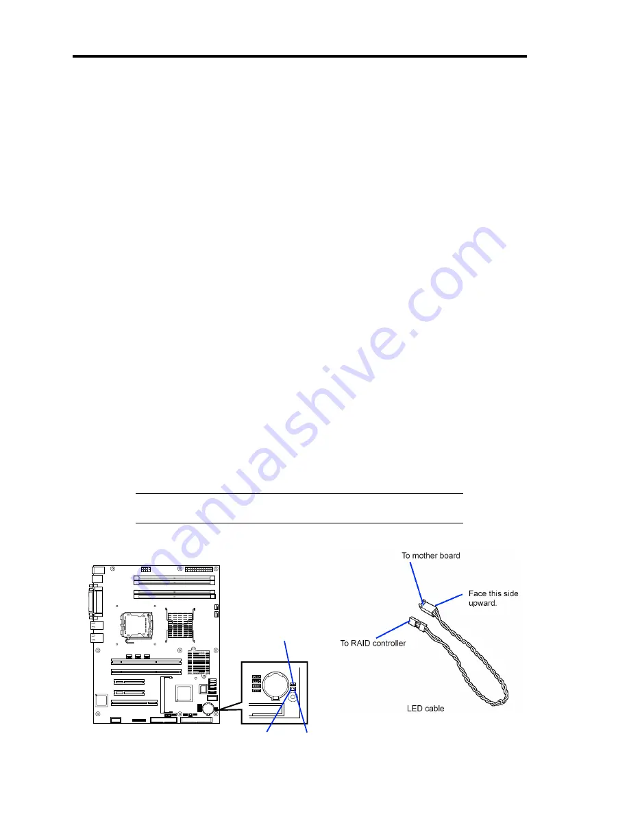
To indicate the access status of each hard disk drive connected to the RAID controller
with the DISK ACCESS lamp on the front panel of the server, use the LED cable that
comes with your server to connect the LED connectors on the mother board and RAID
controller.
NOTE:
Be sure to use PCI slot #1 to install the PCI board for boot
device.
LED connector
Mother board
Red
Black
Summary of Contents for EXP200
Page 162: ...5 56 Installing the Operating System with Express Setup This page is intentionally left blank ...
Page 196: ...6 34 Installing and Using Utilities This page is intentionally left blank ...
Page 208: ...7 12 Maintenance This page is intentionally left blank ...
Page 300: ...10 14 Internal Cabling Diagrams This page is intentionally left blank ...
Page 304: ...A 4 Specifications This page is intentionally left blank ...
Page 370: ...G 4 Product Configuration Record Table This page is intentionally left blank ...


