background image

Viper TX – Operation Instructions


27 

AP-75710, Rev. 1.1, 09/01/2008 


3.4  INSTALLING THE PRINTER 

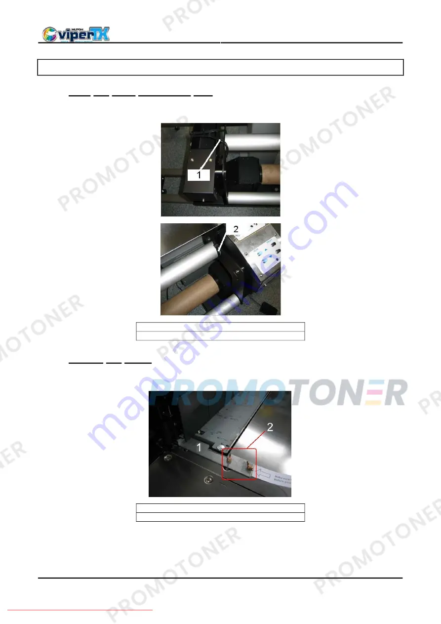
3.4.1 Free the front tensioning bar. 


Cut the cable ties on both sides of the swingbar. See images below. 


1 = Cable tie on the left side 
2 = Cable tie on the right side 


3.4.2 Unlock the head. 


Step 1 : 

Remove the wing screws (2) and the head lock bracket (1). See image below. 


1 = Head lock bracket 
2 = Screws 


Step 2 : 

Remount the wing screws after the bracket has been removed. 


Step 3 : 

Store the bracket in a safe place for future use. 


Downloaded From ManualsPrinter.com Manuals

Summary of Contents for Viper TX

Page 1: ...Operation instructions Downloaded From ManualsPrinter com Manuals ...

Page 2: ...Viper TX Operation Instructions 2 AP 75710 Rev 1 1 09 01 2008 This page is intentionally left blank Downloaded From ManualsPrinter com Manuals ...

Page 3: ...cument the party to whom it is given assumes its custody and control and agrees to the following The information herein contained is given in confidence and any part thereof shall not be copied or reproduced without written consent of Mutoh Europe N V This document or the contents herein under no circumstances shall be used in the manufacture or reproduction of the article shown and the delivery o...

Page 4: ...Viper TX Operation Instructions 4 AP 75710 Rev 1 1 09 01 2008 This page is intentionally left blank Downloaded From ManualsPrinter com Manuals ...

Page 5: ...ry e g rotary screen printers and drop on demand inkjet narrows considerably One application possibility in the field of digital fabric printing is direct fabric printing Mutoh s Viper TX Printers are offered in two different models i e 65 1653 mm fabric width and 90 2280 mm fabric width The Mutoh Viper TX Printers incorporate a heavy duty motorized unwinding winding system for perfect fabric hand...

Page 6: ...Viper TX Operation Instructions 6 AP 75710 Rev 1 1 09 01 2008 This page is intentionally left blank Downloaded From ManualsPrinter com Manuals ...

Page 7: ...arts list 22 3 1 2 Commercial kit 22 3 1 3 Installation kit 22 3 1 4 Viper TX Maintenance Good shape kit for 6 months autonomy 22 3 1 5 Kit with cleaning cassettes 23 3 1 6 Kit with open cassettes 23 3 1 7 Optional parts 23 3 2 CHOOSING A PLACE FOR THE PRINTER 24 3 3 TRANSFER AND TRANSPORTATION 25 3 3 1 Transferring the printer 25 3 3 2 Transporting the printer 26 3 4 INSTALLING THE PRINTER 27 3 4...

Page 8: ...61 4 6 4 Installing the ink collectors 62 4 7 USING THE INK ABSORBENTS 63 4 7 1 Installation 63 4 7 2 Maintenance 63 4 8 INSTALLING PRESSURE ROLLER DISABLER TOOLS 64 5 MAINTENANCE 65 5 1 INTRODUCTION 65 5 2 REPLACING CONSUMABLES 65 5 2 1 Replacing ink cassettes 65 5 2 2 Replacing the waste liquid tank 67 5 3 MAINTENANCE DONE BY END USER 68 5 3 1 Periodical maintenance for the end user 68 5 3 2 Wip...

Page 9: ... on the degree of risk or the scale of accident Read the following explanations carefully and follow the instructions in this manual Safety terms Details Important Must be followed carefully to avoid death or serious bodily injury Caution Must be observed to avoid bodily injury moderately or lightly or damage to your equipment Notes Contains important information and useful tips on the operation o...

Page 10: ...ire Stop using your printer if a liquid is spilled into it This may cause electrical shock or fire Turn the printer off as soon as possible unplug the power cord contact your local MUTOH dealer Be sure to use the attached cable Otherwise electrical shock or fire may occur Be sure to use the specified voltage AC 100 V to 120V or AC 220V to 240V Otherwise electrical shock or fire may occur Use elect...

Page 11: ...can cause burns Have four or more people unpack and assemble the printer Have two or more people transport the printer Ensure that the plug has been disconnected from the power socket when it is not to be used for a long time Earth wires must be connected to wires or terminals that fulfil the conditions below o Earth terminals of power sockets o Earth wires with copper morsel that is at least 650 ...

Page 12: ...ing labels Be sure to note the following when handling the labels Notes Make sure that all labels can be recognized If text or illustrations cannot be seen clearly either clean or replace the label When cleaning labels use a cloth with water or neutral detergent Do not use a solvent or gasoline If a warning label is damaged lost or cannot be recognized replace the label When replacing warning labe...

Page 13: ...Viper TX Operation Instructions 13 AP 75710 Rev 1 1 09 01 2008 No Type 1 2 3 4 Maintenance label Downloaded From ManualsPrinter com Manuals ...

Page 14: ... 2008 1 5 3 Warning labels on rear side No Type 1 CAUTION THIS UNIT HAS TWO POWER SUPPLY CORDS WHEN WINDING UNIT IS PROVIDED TO REDUCE THE RISK OF ELECTRICAL SHOCK DISCONNECT ALL POWER SUPLY CORDS BEFORE SERVICING 2 Downloaded From ManualsPrinter com Manuals ...

Page 15: ...15 AP 75710 Rev 1 1 09 01 2008 1 5 4 Instruction labels on the winder system Roll unit handle label Foot switch label Front tensioning label Rear tensioning label PCB box label Swingbar label Downloaded From ManualsPrinter com Manuals ...

Page 16: ...tion 1 BEFORE powering on printer REMOVE clamp from waste tubes On right bottom side of machine Remove dummy cassettes before powering on the printer 2 BEFORE powering on printer REMOVE clamps from waste tubes 3 BEFORE powering on printer REMOVE dummy cassettes You can also find a label on each of the 8 dummy cassettes Dummy cassette please remove before powering on the printer Downloaded From Man...

Page 17: ... users from electric shocks caused by touching the internal electrical parts The cover is opened when expansion memory optional has to be installed and is closed for normal use 6 Stand Used to install the printer on a flat surface Standard with the unit is the UW W 100 7 Gutter To catch the rest ink 8 Foot switch Used to control the UW W 100 9 Additional coated feeding cylinder Support the fabric ...

Page 18: ...ce board attaches here 6 Interface slot 2 7 Interface slot 3 This is not used for this printer Close it with the cover 8 Hard disk slot The hard disk attaches here When not using a hard disk keep the cover closed 9 Nameplate rating The type name serial number rating and other details of the printer are labelled here 10 Interface slot 4 This is not used It is for future expansion 2 1 3 Operation pa...

Page 19: ... new parameter value and changes the LCD monitor display to the next menu Sets the parameter value and changes the LCD monitor display to the next menu 7 POWER key Turns the printer on and off Switches the printer ON and OFF 2 LCD monitor and status lamps No Name Colour Status Function 8 LCD monitor The monitor displays the operation status and error messages of the printer Flashing An error has o...

Page 20: ...de Manual 3 Unwinder 100 LED Automatic LED lights up when pushing one of the buttons Motor turns LED flashes Motor is off LED is out Outside printing Inside printing 4 Backwards button Roll off unwinder Roll up unwinder 5 Forwards button Roll up unwinder Roll off unwinder Manual 6 Winder 100 LED Automatic LED lights up when pushing one of the buttons Motor turns LED flashes Motor is off LED is out...

Page 21: ...se as possible to the installation location to avoid unnecessary transportation of the unpacked printer Starting point Unpacked items Step Action 1 Unpacking 2 Verifying the packaged items 3 Choosing a place for the printer 4 Transfer and Transportation 5 Installing the printer 6 Calibrating the Winder system 7 Connecting the printer 8 Connecting the cables of the winding system Result FULLY INSTA...

Page 22: ... 4 Fian software 1 5 Maintenance label set Viper TX 1 6 Power cable 1 x EU 1 x UK 1 x US 3 1 3 Installation kit No Item Quantity 1 UW100 TX Alignment tool 1 2 Polyester strip 1 3 Motor twist cable 1 4 Alignment spacer 10 5 Hex Key 5 long 1 6 Hex Wrench 4 Ball 1 7 Hex Key 3 1 8 Hex Key 2 5 1 9 Instruction Sheet IR Heater 1 10 Bump Plate for IR Heater 2 11 Foot switch Winder system 1 12 Foot switch ...

Page 23: ...ter based textile cleaning liquid 220 ml cassettes 3 1 6 Kit with open cassettes No Item Quantity 1 Open cassettes 16 2 Funnel 16 3 Box maintenance kit 1 3 1 7 Optional parts No Item Quantity 1 Infra Red dryer Stand with heater 2 Water based disperse dye ink 220 ml cassette Downloaded From ManualsPrinter com Manuals ...

Page 24: ...ink tubes and without condensation Required space 12 7m 144ft or larger Frontage of 4 7m 15 7ft or greater For 65 model 14 3m 162ft or larger Frontage of 5 3m 17 7ft or greater For 90 model Viper TX 65 Length 3069 mm Width 720 mm Height 1221 mm Viper TX 90 Length 3639 mm Width 720 mm Height 1221 mm Notes Avoid the following temperature and humidity conditions Otherwise printed images may appear di...

Page 25: ...r transport is not covered by the warranty Have two or more people to transport the printer 3 3 1 1 Before the transfer If you are using the stand follow the steps below to transfer the printer Step 1 Make sure the printer is turned off Step 2 Make sure the UW W 100 system installed onto the stand is turned off Step 3 Make sure the head is in the right edge position capping position Step 4 Disconn...

Page 26: ...er s guide Step 5 Perform a nozzle check to check the printer s heads Notes To perform the nozzle check refer to Nozzle check menu Step 6 Perform a fine adjustment of image quality Notes To perform an adjustment of image quality refer to Testprint menu 3 3 2 Transporting the printer When you transport the printer the printer should be repacked in the original box and packing materials to protect i...

Page 27: ...gbar See images below 1 Cable tie on the left side 2 Cable tie on the right side 3 4 2 Unlock the head Step 1 Remove the wing screws 2 and the head lock bracket 1 See image below 1 Head lock bracket 2 Screws Step 2 Remount the wing screws after the bracket has been removed Step 3 Store the bracket in a safe place for future use Downloaded From ManualsPrinter com Manuals ...

Page 28: ...el Step 3 Place the level on the left and right side of the printer s stand and level the printer sides by turning the feet under the stand The image below shows the Y leveling direction PART 2 Level the printer in X direction Step 1 Position the level on the print platform Step 2 Turn the left and right weight supports an equal amounts of turns See image below Notes Make sure to turn the left and...

Page 29: ...cil 1 3 5 1 1 Checking the calibration The procedure below describes the calibration check of the rear tensioning system The procedure to check the front tensioning system is the same PART 1 PREPARING THE SYNTHETIC PAPER STRIP Step 1 Put the pressure rollers in the up position Step 2 Go to the back of the machine Step 3 Create a loop with the synthetic paper strip around the upper bar of the rear ...

Page 30: ...E of the printer Step 7 Carefully pull the strip until it is a little tensioned Caution Don t pull too hard on the strip This will loosen the tape resulting in the fact that the loop becomes longer leading to a bad calibration check Make sure that you have an equal tension on the left and right of the strip PART 2 DRAWING THE CONTROL LINES Step 1 Place the adjustment plate onto the strip and slide...

Page 31: ...g at the FRONT SIDE carefully pull the strip so there is an equal tension on it Caution Don t pull too hard on the strip This will loosen the tape resulting in the fact that the loop becomes longer leading to a bad calibration check Make sure that you have an equal tension on the left and right of the strip Step 5 Place the adjustment plate onto the strip and slide it against the pressure rollers ...

Page 32: ...O gap between the lines no adjustment is necessary For the adjustment procedure refer to the next topic Adjusting the tensioning systems 3 5 1 2 Adjusting the tensioning systems Introduction The present topic describes the adjustment of the REAR tensioning system The procedure to adjust the front tensioning system is the same Procedure Step 1 Standing at the REAR SIDE of the unit remove the cover ...

Page 33: ...the tension bar bracket to adjust the tension system Tool Hexagon wrench 3 mm 1 Adjustment screws IF Line 2 lays THEN turn the adjustment screws as follows BEFORE line 1 Case A on image above BEHIND line 1 Case B on image above Important Make sure to turn both adjustment screws an equal amount of turns Step 4 Check the calibration again and repeat the adjustment until the lines overlap each other ...

Page 34: ...The procedure below describes the calibration check of the FRONT roll unit The procedure to check the rear roll unit is the same In the procedure line 1 is drawn at the RIGHT side of the printer line 2 at its LEFT side PART 1 PREPARING THE SYNTHETIC PAPER STRIP Step 1 Put the pressure rollers in the up position Step 2 Install an empty core between the roll unit and the motorized roll unit at the f...

Page 35: ...r strip 2 Loop 3 Core 4 Pressure rollers Caution Don t pull too hard on the strip This will loosen the tape resulting in the fact that the loop becomes longer leading to a bad calibration check Make sure that you have an equal tension on the left and right of the strip PART 2 DRAWING THE CONTROL LINES Step 1 Standing at the front side of the unit place the adjustment plate onto the strip and posit...

Page 36: ...tep 4 Place the adjustment plate onto the strip and slide it against the pressure rollers Step 5 Pull the strip so there is an equal tension Caution Don t pull too hard on the strip This will loosen the tape resulting in the fact that the loop becomes longer leading to a bad calibration check Make sure that you have an equal tension on the left and right of the strip Downloaded From ManualsPrinter...

Page 37: ...2 lines and do the correct action IF there is THEN a gap between the lines perform the adjustment procedure NO gap between the lines no adjustment is necessary For the adjustment procedure Refer to Adjusting the roll units 3 5 2 3 Adjusting the roll units Procedure Step 1 Use the correct amount of spacers 2 to cover the space between the drawn lines 1 1 Drawn lines 2 Spacer Downloaded From Manuals...

Page 38: ... Adjusting the REAR Units IF line 2 lays THEN BEFORE line 1 add spacers on the left rear unit or remove spacers on the right rear unit BEHIND line 1 remove spacers on the left rear unit or add spacers on the right rear unit Step 3 Insert these spacers 1 at the left or right side depending on the deviation determined in the previous step BETWEEN the roll unit bar 3 and the printer s stand 2 1 Space...

Page 39: ...der the UW W 100 Parts and Tools No Description Quantity 1 Hexagon wrench 3 mm 1 3 5 3 1 Location of the weight supports on a 65 printer There are 2 weight supports on the UW W 100 system for a 65 machine FRONT VIEW 1 Weight support 3 5 3 2 Location of the weight supports on a 90 printer There are 4 weight supports on the UW W 100 system for a 90 machine FRONT VIEW 1 Weight support Downloaded From...

Page 40: ...ts Caution Don t turn the weight supports with force when they reach the floor Instructions Lower the weight supports of the UW W 100 till they reach the floor A hexagon wrench 3 mm can be used 1 Hexagon wrench 3 mm 2 Turning direction to lower the support Downloaded From ManualsPrinter com Manuals ...

Page 41: ...depending on the type of applications you are using and the complexity of the document you want to print MUTOH recommends you to use a hard disk and RAM memory as large as possible 3 6 1 2 Selecting cables This printer is compatible with following interfaces Centronics interface Network interface The following cables are necessary to connect your printer to the computer Prepare appropriate cables ...

Page 42: ...otes Refer to your computer s manual for the procedure to connect to your computer 3 6 1 4 Connecting the network interface Caution Follow the instructions below when connecting the network interface cable Otherwise electrical shock or fire may occur o Do not touch the connector o Do not connect the network cable connector to the interface board having different specifications The procedure for co...

Page 43: ... the foot switch with force and do not pull o Do not place the foot switch near thermal devices Install the foot switch according to following procedure Step 1 Make sure that the power of the unit is OFF Notes When the operation panel is in the following condition the power is ON Press the key again to turn the power OFF o The POWER lamp is lit green Step 2 Connect the foot switch cable connector ...

Page 44: ...following areas o Gas pipes Doing so may cause fire or an explosion o Earth terminals for telephone lines or lightning rods Doing so may cause a large flow of voltage if lightning occurs o Water pipes or faucets If there is a plastic part in the pipe the earthing will not work correctly Caution Follow the instructions below when handling the power plug Otherwise fire may occur o Wipe away dust and...

Page 45: ...tes If the power cable is damaged contact one of the following o The distributor where you bought your MUTOH printer o Your local MUTOH dealer Notes If you cannot use earth terminals or find any of them contact the shop where you bought your printer Do not unplug the power cable when the printer is on If the power cable has been unplugged leave the printer for at least 1 minute before plugging the...

Page 46: ...ector 1 Step 2 Check if the all cables of the UW W are connected to the correct connector 1 to 6 See image below for the location of the connectors 1 Operation panel connector 2 Foot switch connector 3 Front motorized unit connector 4 Rear motorized unit connector 5 Power supply connector 6 PCB Box 7 Not used Notes With a small intervention it is possible to reverse your winding direction Mount th...

Page 47: ... GENERAL PROCEDURE Starting point FULLY INSTALLED VIPER TX Step Action 1 Switching ON the power of both printer and UW W 100 2 Verifying the Printer Status 3 Installing ink cassettes 4 Handling and installing the fabric 5 Installing fabric retainers or ink collectors 6 Using the ink absorbents 7 Installing the pressure roller disabler tools 8 Testprinting Optional Result READY TO PRINT VIPER TX Do...

Page 48: ...tching the power ON Printer Step 1 Press the POWER key of the operation panel to turn the unit ON The arrow on the image below indicates the POWER key The POWER LED 1 of the operation panel will light green 1 Power LED Step 2 Wait until the unit has initialized Notes If there are any problems during the initial start up operation the unit will display a message on the operation panel and the opera...

Page 49: ...he POWER key indicated by the black arrow on the image below of the operation panel to switch the printer OFF Step 3 Wait while the following message is displayed for 3 seconds on the operation panel Power OFF Notes If the POWER key on the operation panel is pressed by mistake during the power off cycle press the POWER key again Step 4 Wait until the printer performs its power OFF operation displa...

Page 50: ...ak Notes The unit is delivered shipped with special shipping liquid to prevent air coming into the ink supply system Make sure that air never enters the ink supply system Caution Before powering ON the unit for the first time make sure to o Remove the dummy cassettes o Remove the waste tube clamps o Remove the bag enclosing the waste tubes o Connect the waste tubes o Unlock the head station Refer ...

Page 51: ...2 Check if the Waste Bottle is empty Step 3 Power ON the unit Caution The unit is shipped with a water based shipping liquid Step 4 In the Ink Manager menu select Wash and then select All Confirm your selection The display will ask you to install the cleaning cassettes Please insert Cleaning Cart Install the 8 NEW Mutoh Water based Textile cleaning cassettes 1 Ink cassette slot 2 Cleaning cassette...

Page 52: ...ng Wait for a while 0 min Step 8 The display will show the following message Please remove cartridges Step 9 Remove all the cleaning cassettes compatible with the ink Ink status No cartridge ALL Step 10 Insert ink cassettes in the required configuration The ink cassettes must be inserted in a specific slot according to the type and colour used Insert the cassettes with the arrow mark face up and p...

Page 53: ...ep 13 Set the smartchip mode to Mutoh or Manual Mutoh mode automatic recognition Manual mode Colour mode is set manually by the user Select Smart ship in the Ink Manager menu Select Manual or Mutoh in the Smart chip menu In Manual mode select appropriate colour mode Caution If the smartchip detection is set to manual please make sure to select the correct colour mode If not the printer will not wo...

Page 54: ...n in the images below Step 2 Position the fabric roll in the middle of the printing space Use the numbers indicated on the roll unit bar to position the fabric roll See image below 1 Fabric roll 2 Numbers on the roll unit bar Step 3 Position the roll units of the unwinder in such a way that the fabric roll can be placed in between 1 Roll unit handle 2 Roll unit 3 Fabric roll Step 4 Lock one roll u...

Page 55: ...ore between the motorized roll unit and roll unit of the winder unit on front of the printer Notes We recommend to wear cotton gloves to avoid fingerprints on the inkjet fabric 4 5 2 Loading the fabric into the printer Procedure Step 1 Verify that the printer and UW W 100 are both ON the front cover of the printer is open and the pressure rollers are in the UP position Step 2 Set the both unwinder...

Page 56: ... Rear tensioning system 3 Fabric 4 Insertion slot 5 Pressure roller bar Step 6 Set the unwinder rear to OFF Step 7 On front of the printer take the center of the fabric and pull straight down until you obtain an equal tension on the left and right of the fabric Notes Make sure the rear tensioning system is lifted against the unit Downloaded From ManualsPrinter com Manuals ...

Page 57: ... foot switch of the UW W 100 to roll off fabric during loading of the roll fabric 4 5 3 Setting Fabric type Step 1 Switch the printer on and load the fabric Once the fabric has been set the Fabric Initial menu will be displayed FabricInitialMenu Roll F2 F3 LeverUp User1 F4 F2 F4 ENTER or F3 Notes Refer to following section to load fabric Loading the fabric into the printer Step 2 Press one of the ...

Page 58: ...ser 1 Notes The printer starts the Fabric initialization operation if you o Press the CANCEL key on the operation panel o Leave the printer for 10 seconds without doing anything Step 4 When the Fabric initial operation finishes the printer moves to normal status The setting fabric loading procedure has been completed The display returns in the normal status Ready to print Feed Cleaning Cancel Leve...

Page 59: ... the fabric s border is fully positioned under the top plate of the fabric retainer Make sure the fabric does not sag or catch the fabric retainer Place the fabric retainers BEFORE fabric initialisation 4 6 1 When using fabric without self edge Fabric without self edge The fabric has fringes on the edges See image below 1 Fringes 2 Print direction Print tool needed Fabric retainers Purpose Too kee...

Page 60: ...THEN the edge printing feature is NOT used use FABRIC RETAINERS Instal them before fabric initalisation the edge printing feature is used use INK COLLECTORS Instal them after fabric initialization Do NOT use fabric retainers Purpose Fabric retainers To keep the edges of the fabric down to the printplatform in order to prevent contact with the heads Ink collectors To capture the ink jetted next to ...

Page 61: ...e sure the fabric does not sag or catch the fabric retainer Place the fabric retainers BEFORE fabric initialisation Step 1 Place the border of the fabric under the fabric retainer s top plate 1 Border fabric 2 Top plate of fabric retainer 3 Fabric retainer Step 2 Perform the fabric initialisation by switching the lever up after that switching it back to the down position Notes Set to Rollfeed on t...

Page 62: ...alling the ink collectors Placement TOP VIEW 1 Fabric edges 2 Fabric 3 Print direction 4 Ink collectors SIDE VIEW 1 Fine metal mesh 2 Mesh fixer 3 Fabric 4 Additional feeding cylinder coated 5 Mesh holder 6 Gutter 7 feeding cylinder Downloaded From ManualsPrinter com Manuals ...

Page 63: ...iners 4 7 1 Installation Edge to edge printing Regular printing When printing edge to edge you will print wider than the media width Maximum 5 cm at both sides Position the absorbent until you have an extra 1 cm So in this case 6 cm When leaving a margin while printing and you do not need to use the fabric retainers it is recommended to install the absorbents under the left and right edge of the f...

Page 64: ...edure Step 1 Take the Pressure roller disabler tool as follows in your right hand See image below Step 2 At the back of the printer pull the pressure roller you want to disable down with your left index finger Step 3 Place the Pressure roller disabler tool in the space created when pulling the pressure roller down See image below Result The Pressure roller disabler tool is now positioned as follow...

Page 65: ...cassette is low Printing operation is continued Prepare new ink cassettes before they are totally empty The following message is displayed on the operation panel Ready to Print Feed Cleaning Cancel LeverUp NearEnd 1 Slot number corresponding with the almost empty cassette b The ink cassette becomes empty Printing operation stops Replace with a new ink cassette as soon as possible The following mes...

Page 66: ... off Step 2 Open the ink compartment cover Caution Be sure not to pinch your fingers while opening and closing the ink compartment cover Step 3 Remove the ink cassette from the ink cassette slot Notes Dispose the used ink cassette by putting it in a plastic bag in accordance with local regulations or laws Step 4 Take the new ink cassette from its package Step 5 Install the ink cassette Step 6 Clos...

Page 67: ...n panel is off Step 2 Follow Menu setup on the operation panel TankChg No Yes F2 1 1 Changed wasted ink tank ENTER or CANCEL Step 3 Open the cap of the waste liquid tank Caution Do not bend or pull the waste fluid tube Doing so may cause that the waste fluid to leak out and damage the printer Step 4 Remove the waste liquid tank from the tank tray of the stand Notes Put the used waste liquid tank i...

Page 68: ...ult in damage or paint peeling from the casing Be careful not to spill liquid inside the printer Doing so may result in a short circuit Never open the covers fixed with screws Doing so may result in electrical shock or malfunctioning of the printer Notes Please make sure to wear gloves when Handling the cleaning liquid Using the dust free clothes 5 3 1 Periodical maintenance for the end user These...

Page 69: ...mpty 1 4 Mutoh water based textile cleaning liquid 500 ml 2 5 Instruction sheet 1 6 Good shape kit KY 80228 See below for content of the kit 1 5 3 1 2 Content of the Good shape kit Good shape kit KY 80228 No Item Quantity 1 Box of gloves 100 per box 3 2 Pipettes 20 per box 3 3 Swabs 3 x 50 4 Polyknit Wiper 300 Mutoh water based textile cleaning liquid is available in the following quantities MY 80...

Page 70: ...y on the operation panel shows the normal status The FABRIC SET light on the operation panel goes off Step 2 Follow Menu setup on the operation panel and display the cleaning wiper menu on the operation panel SetupMenu F1 H Unlock WiperClean F2 F3 TankChg TubingFlush F4 6 7 WiperClean No Yes F2 1 1 Step 3 Select Yes by pressing the F2 key on the operation panel The printer enters the cleaning wipe...

Page 71: ...The carriage moves to the cap position The printer returns to menu 6 7 SetupMenu F1 H Unlock WiperClean F2 F3 TankChg TubingFlush F4 6 7 The printer returns to the normal status after pressing the CANCEL key Ready to Print Heaters Cleaning Feed LeverUp User1 xxxm 5 3 3 Clean the ink gutter at shutdown When to perform The ink gutter needs to be cleaned daily when shutting down Caution Wear protecti...

Page 72: ...rinsing bottle to rinse the gutter and the drain with water Step 2 Dry the gutter with paper Notes When using the feature of edge printing the ink collector must be used After use the ink collector can be rinsed with water from the rinsing bottle Downloaded From ManualsPrinter com Manuals ...

Page 73: ...cap position Procedure Step 1 Perform a tubing flush F4 in Menu 6 7 SetupMenu H Unlock WiperClean TankChg TubingFlush F4 6 7 Step 2 Press the F1 button The pumps will start for cap 1 4 5 8 TubingFlush F1 Head 1 2 Head 3 4 1 1 Step 3 Flush caps 1 4 5 8 with Mutoh water based textile cleaning liquid until the colour of the mousse in the cap does not change anymore Step 4 Let the pumps run for 10 mor...

Page 74: ... return to the capping station 5 3 5 Clean the Spitting box mesh When to perform The spitting box mesh must be cleaned daily Important Do not insert or drop metal or inflammable objects into openings such as ventilation outlets Doing so may result in electrical shock and fire Stop using your printer if a liquid is spilled into it This may cause electrical shock or fire Power the printer OFF as soo...

Page 75: ...Important Never touch the unsupported mesh Touching the unsupported mesh will deform it irreversibly Always take the mesh by its sides 1 Unsupported and supported side of the mesh 1 unsupported mesh 2 supported part of the mesh 2 Handling the mesh Downloaded From ManualsPrinter com Manuals ...

Page 76: ...position for cleaning the mesh Step 3 Push one corner of the supported mesh down Step 4 Grab the mesh by the sides and take it out as shown in the image below Step 5 Rinse the mesh with Mutoh water based textile cleaning liquid until the ink is removed Step 6 Place the clean mesh on a dust free cloth for 1 minute to drain most liquid Step 7 Rinse the spitting box with water use the rinsing bottle ...

Page 77: ...ing around the heads When to perform Cleaning around the heads must be performed weekly Caution Only use Mutoh water based textile cleaning liquid Only use swabs of the Good shape kit Step 1 Power ON the printer and go to the WiperClean Setup Menu This will cause the unlocking of the carriage WiperClean Changed wiper ENTER Step 2 Open the left maintenance covers by loosening the four screws Step 3...

Page 78: ...r based textile cleaning liquid Make sure you do not touch the nozzle plate this would lead to bad print quality Caution Do not touch the nozzle plate 1 Cleaning swab 2 Glove Step 5 Press the ENTER key when done The carriage will automatically go to its home position WiperClean Changed wiper ENTER Downloaded From ManualsPrinter com Manuals ...

Page 79: ...hock or malfunctioning of the printer 1 Cleaning the outer case Remove dust or smudges on the outer case with a soft cloth 2 Cleaning the inside of the printer Step 1 Open the front cover Step 2 Use a soft brush to carefully clean away any dust or dirt Notes Do not blow off fabric dust inside the printer using compressed air Doing so may cause noise to occur from inside the printer Caution Please ...

Page 80: ...Step 1 Power ON the printer and go to the Head Unlock setup menu This will cause the unlocking of the carriage H Unlock To lock heads press ENTER Step 2 Remove the two screws fixing the sponge 1 Screws to remove the capping sponge from the plate Step 3 Replace the sponge and tighten it again to the plate with the two screws 1 Capping sponge 2 Plate Downloaded From ManualsPrinter com Manuals ...

Page 81: ... hands while cleaning the cleaning wiper Doing so may result in poor head cleaning because of oil on your hands Wear protective gloves Do not move the position of the wiper arm forwards backwards to prevent error generating when head returns to the cap position Notes Please refer to the section Periodical Services To replace the wipers please follow the instructions mentioned below Step 1 Remove t...

Page 82: ...ER PATH CARRAIGE if needed 4 APPLY GREASE ON CAPPING STATION CAMM GEARS if needed 5 Replace all caps Every 3 months 6 Replace the tubes connecting the pumps to waste bottle Every 3 months 7 CHECK Cylinder Supporting bearings every 6 months 8 CHANGE PUMPS every 6 months 9 CHECK and RELACE when necessary SPITTING BOX RIGHT TUBE L CONNECTION every 6 months 10 CHANGE DAMPERS every year 11 CHANGE MAINT...

Page 83: ...4th line Displays the currently set fabric type 7 Right of 4th line Displays the approximate amount of remaining fabric that is currently set Units m However the amount is displayed only when either Roll fabric 1 Roll fabric 2 or Roll fabric 3 is selected in the Roll fabric setting menu 6 1 2 Setup menu display In the Setup menu changes can be made to the printer settings The contents displayed on...

Page 84: ...nging the printer status To change the printer status follow the steps below 6 1 4 1 Changing the status from normal to the setting menu display Press either MENU Ç or MENU È on the operation panel when the printer is in normal status The display of the operation panel changes to the Setting menu display 6 1 4 2 Changing the status from the setting menu display to normal Take one of the following ...

Page 85: ...print menu Fabric setup menu Fabric type menu InkDryTime H Height Thickness Dist adj Topfeed Menu 2 7 Printing mode menu Printing mode menu ColorMode 6Col LcLm 6Col 0G 8Color Condition Direction UniDir BiDir HeadSet Native 1234 Set 5678 Set Alternate Double D RepeatPrn Downloaded From ManualsPrinter com Manuals ...

Page 86: ...Set 1 Weave Set 2 Weave Set 3 Stitch Off Sign Quality Picture Speed ScanWidth DataWidth MediaWidth FullWidth Command Setup menu Step Resolu OnlineTimer Layout setup menu Joint printing menu Function setup menu CMY K Menu 3 7 RollSetup Centro Centro BiCentro Downloaded From ManualsPrinter com Manuals ...

Page 87: ...ss SubnetMask Gateway Menu 4 7 Utility ErrorDisp FabricDet StartPow MediaWidth OnCleaning SlantCh Prn Wipe AutoClean EdgePrn FileMng WriteMode Reprint Delete Rename Format Initial All FabricSet PrintMode Command Layout Function RollSetup Downloaded From ManualsPrinter com Manuals ...

Page 88: ...08 Centro Network Utility FileMng Menu 5 7 DataDump InkManager Smart Chip Mutoh Manual Wash Pump 1 2 Pump 3 4 ALL InkLoad Pump 1 2 Pump 3 4 ALL Menu 6 7 H UnLock WiperClean TankChg TubingFlush Menu 7 7 VersionCheck Area Downloaded From ManualsPrinter com Manuals ...

Reviews: