


Spline interpolation
Appendix-671
7.3.8 Saving in the robot controller
Save the robot program and spline file into the robot controller.
Refer to
Page 648, "(9) Saving the spline file"
for details on saving the spline file.
7.3.9 Adjustment work
Using the actual system, confirm the spline interpolation movement with debugging (step feed).
If the movement differs from the required movement, review and revise the path point data and robot pro-
gram. To revise the path point data, import the spline file into the RT ToolBox 2 Spline File Edit screen and
change the path point data setting values. Then, export the file to the controller.
The "position adjustment function", "frame transformation function", and "position jump function" provided in
the RT ToolBox2 for adjusting the position data, and the parameter SPLOPTGC (active gain control gain
compensation rate) are explained in this section.
(1) Position adjustment function
The same type of adjustment as the MELFA-BASIC V position data's relative calculation can be applied on
the path point data's robot position. The two compensation methods shown in
can be used.
Table 7-19:Position adjustment method
Adjustment method
Explanation
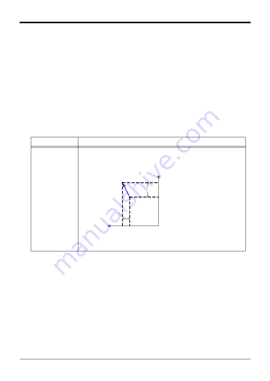
Vector sum operation
(P+P)
The adjustment data value is added (addition of each coordinate element) in respect to the path point
data's robot position data. The adjustment goes along the world coordinate system.
The configuration flag, multi-rotation flag and additional axis data are not changed from the original
value.
Xw
Yw
PA
PB
PC.X
PC.Y
ベクトル和演算(P+P)
PA:補正対象の経路点
PB:補正結果
PC:補正データ
Vector sum calculation (P+P)
PA: Path point for adjustment target
PB: Adjustment results
PC: Adjustment data


