


Coordinate system description of the robot
4-149
4.5.3 About position data
Positional data for the robot is comprised of six elements which indicate the position of the hand's leading
end (mechanical interface center where no tool setting is made) (X, Y, and Z) and the robot's posture (A, B,
and C), plus a structure flag.
Each element constitutes reference data for the robot's world coordinate system.
[Meaning] X, Y, Z: Coordinate data. Position of the robot hand's leading end (in mm).
A, B, C: Posture data. Angle that defines the robot's posture (in degrees)
A
→
Angle of rotation on X axis
B
→
Angle of rotation on Y axis
C
→
Angle of rotation on Z axis
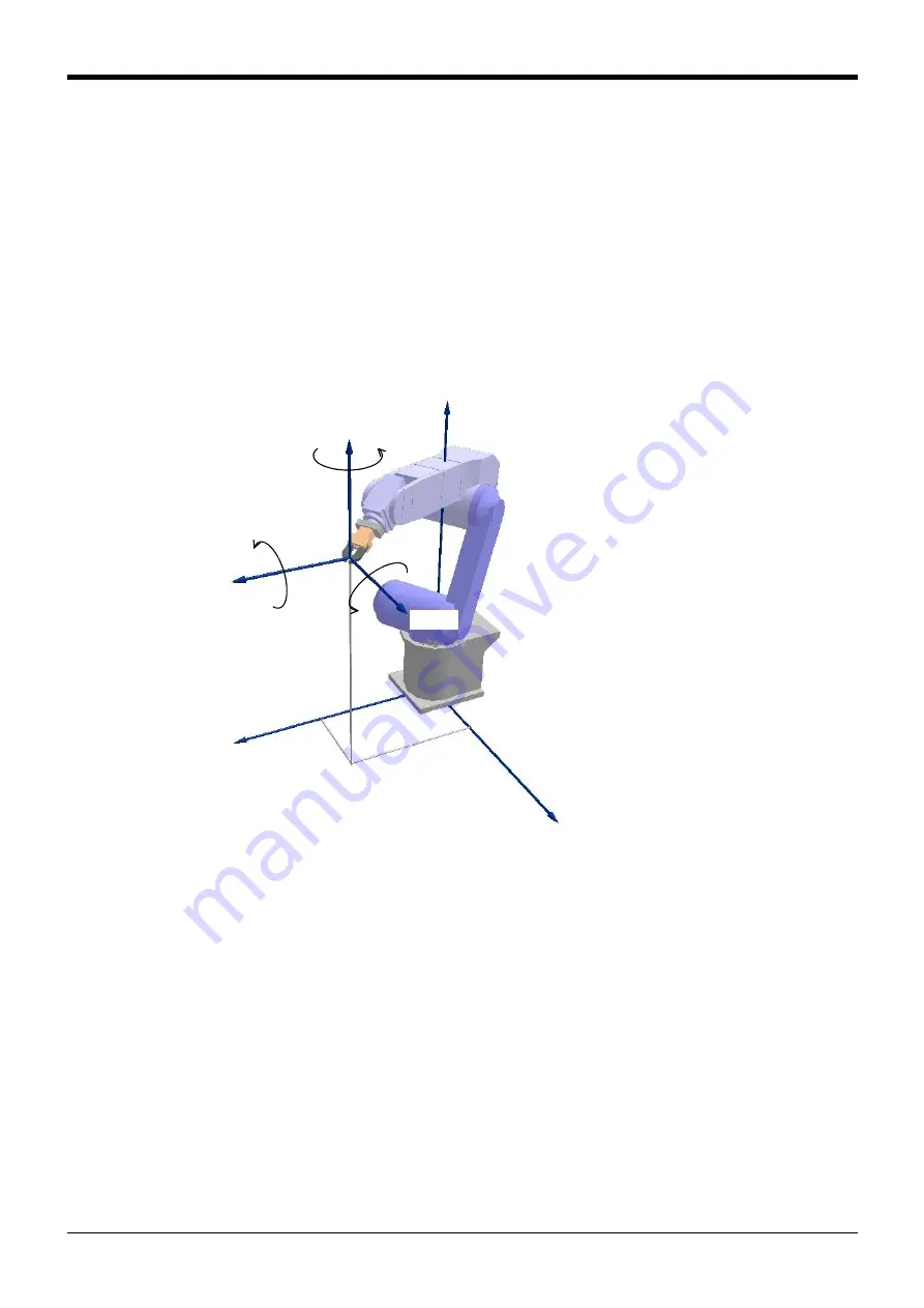
Fig.4-5:Reference for posture angles
A, B, and C represent the robot's posture in the coordinate system of its hand's leading end (or flange
center where no tool setting is made), each indicating a angle of rotation on the X axis, Y axis, and Z axis of
the world coordinate system. Rotation corresponding to the direction of a right-handed screw when you look
at the + side of each coordinate axis is "+" rotation. Also, rotation is set to take place in a predetermined
sequence, and the amount of rotation is calculated (controlled) first for a rotation on the Z axis, followed by
one on the Y axis and one on the Z axis in the order shown.
(Z軸)
Z軸
A
B
C
X軸
(X軸)
(Y軸)
Y軸
X
Z
Y
Note) This diagram is produced by
assuming a situation in which no
base data setting is made, i.e., the
robot's world coordinate system is
in agreement with its base
coordinate system.
(Z-axis)
(X-axis)
(Y-axis)
Z-axis
X-axis
Y-axis


