background image

Set up the Counter

248083387-1 Rev 10

4-3

The setup process is as follows: 

Analog channels are labeled in the settings as A1 through A4. A1 and 
A2 correspond to Analog port 

1

 on the chassis and A3, A4 correspond 

to port 

2

. A1 and A3 are the first channel and A2 and A4 are the second 

channel of these ports. So, if a single-channel sensor is attached to port 

1

 and is wired to connect to channel one, its data will be displayed on 

A1. If it is wired to operate on the second channel, its data will be 
displayed on A2.

If a dual-channel sensor, such as the Lighthouse TRH (temperature, 
relative humidity) probe, is connected to port 

1

, its temperature data 

will show up on A1 and its relative humidity data will be displayed on 
A2.

The setup process is as follows: 

Note:

The screen 

examples in this chapter 
are for visual reference. 
The values displayed may 
not be indicative of actual 
values.

1. From the MAIN Screen, press the CONFIG button. 

2. On the CONFIGURATION screen, press the ANALOG button. 

Note:

The Min and Max 

values for the Lighthouse 
TRH Probe are 0-150. If 
using a TRH Probe other 
than Lighthouse, please 
check the manufacturer’s 
specifications for the 
correct values.

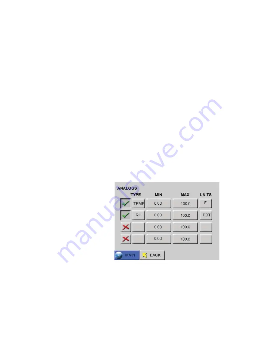
3. The Analog Configuration Screen displays Figure 4-2.

Figure 4-2  Analog Configuration Screen

4. Press the red “

X

” button to enable an analog channel.

Summary of Contents for SOLAIR 3350

Page 1: ......

Page 2: ...00...

Page 3: ...Lighthouse Worldwide Solutions SOLAIR 3350 5350 Gen E Airborne Particle Counters Operating Manual...

Page 4: ...to be disclosed such information except as permitted in writing by Lighthouse Worldwide Solutions The information contained herein is subject to change without notice Lighthouse Worldwide Solutions i...

Page 5: ...Equipment for Measurement Control and Laboratory Use Part 1 General Requirements LASER SAFETY Guidance on Laser Products Conforms to FDA 21 CFR Chapter 1 Subchapter 1 EMC EN61326 Electrical Equipment...

Page 6: ......

Page 7: ...2 1 Description 2 1 SOLAIR 3350 Specifications 2 2 SOLAIR 5350 Specifications 2 3 Chapter 3 Unpack Inspect and Install Initial Inspection 3 1 Unpacking 3 1 Verify Package Contents 3 1 Shipping Instru...

Page 8: ...Requirements 4 17 Configure Device 4 18 Ethernet Port Configuration 4 18 Straight through Cat5 Setup 4 18 Cross over Cat5 Setup 4 19 Program the Interface 4 19 Windows Telnet Programming 4 19 Connect...

Page 9: ...ARM 6 27 Alarm Threshold 6 27 CLEAR BUFFER 6 29 DEVICE SETUP 6 29 CLOCK 6 30 OPTIONS 6 32 CONTRAST ADJUST 6 32 AUDIBLE BEEP ADJUST 6 32 ALIGN TOUCH SCREEN 6 32 AUTOSTART MODE 6 35 DiffCuml on Zoom 6 3...

Page 10: ...1 Communicating with the Instrument 7 1 RJ 45 Comm Port 7 2 RS485 Communications 7 2 RS232 Communications 7 2 USB Communications 7 3 Using the USB Port to connect to a PC 7 3 Configure with the MODBU...

Page 11: ...Units Registers B 12 Data and Alarm Registers B 13 Data and Alarm Enable Registers B 13 Enable Alarming for a Channel B 16 Threshold Setup Registers B 16 Setting the Alarm Threshold Value B 18 Append...

Page 12: ...Lighthouse SOLAIR 3350 5350 Gen E Operating Manual t vi 248083387 1 Rev 10...

Page 13: ...serious personal injury or death and damage to the instrument boldface Introduces or emphasizes a term Courier font Indicates command syntax or text displayed by the diagnostic terminal Bold Courier...

Page 14: ...Lighthouse SOLAIR 3350 5350 Gen E Operating Manual ii 248083387 1 Rev 10...

Page 15: ...DA 21 CFR 1040 10 when used under normal operation and maintenance Performing service on the sensor can result in exposure to invisible radiation WARNING The use of controls adjustments or procedures...

Page 16: ...n expose the instrument power supply adjacent equipment or the user to dangerous shock and fire hazards Failure to heed this warning can result in personal injury or death The international Caution sy...

Page 17: ...meter The 3350 or 5350 uses a laser diode light source and collection optics for particle detection Particles scatter light from the laser diode and the collection optics collect and focus the light...

Page 18: ...e Extreme Life Laser Diode Technology 20 year MTTF Zero Count Level 1 count 5 minutes per ISO 21501 4 Calibration NIST Traceable Count Modes Concentration manual automatic beep Data Storage Stores up...

Page 19: ...battery 26 0 lbs 11 8 kg Operating Temp RH 50 F to 104 F 10 C to 40 C 20 to 95 non condensing Storage Temp RH 14 F to 122 F 10 C to 50 C Up to 98 non condensing Table 2 1 3350 Specifications Size Rang...

Page 20: ...20 Analog ports AC In Supporting Software LMS XChange Data Transfer Software LMS Express Express RT LMSNet Touch Screen Display Color 5 7 14 47 cm 320x240 Optional Printer Thermal printer Reports FS...

Page 21: ...on 248083387 1 Rev 10 2 5 For information about returning instruments for calibration or service please visit our RMA website www golighthouse com RMA Figure 2 1 SOLAIR Dimensions Side Dimensions Top...

Page 22: ...Lighthouse SOLAIR 3350 5350 Gen E Operating Manual 2 6 248083387 1 Rev 10...

Page 23: ...carton for reshipment of the instrument for its annual factory calibration Report damages to Lighthouse Technical Support at 1 800 945 5905 USA Toll Free 1 541 770 5905 Outside of USA before proceedin...

Page 24: ...it to ship separately refer to www golighthouse com rma for detailed instructions Remove attachments such as TRH or Isokinetic probes and package to prevent physical and ESD damage TRH 2 If the origin...

Page 25: ...Pressure Sensor optional plugs into the instrument s rear panel Monitors range from 0 0 5 H2O 124 5 Pa Results are displayed printed if printer is available and can be downloaded using the LMS XChange...

Page 26: ...ave data for historical review 3 Have advanced reporting with standard reports and much more LMS Express RT software optional an analysis tool that allows the user to perform the following 1 Download...

Page 27: ...ighthouse as an option For the single battery units follow steps 1 3 for the dual battery follow steps 4 6 To install the battery s make sure the power switch is in the OFF out position gently lay the...

Page 28: ...partment until it snaps into place See Figure 3 4 Close the door and tighten the screw lock by turning it clockwise Figure 3 4 Battery Engaging Connector 4 For the dual battery units Open the battery...

Page 29: ...ockwise Connect the SOLAIR to AC Power To charge the battery once it is installed or to operate the 3350 5350 on AC power plug the unit into an AC power source the battery will start charging To opera...

Page 30: ...n the power switch OFF 2 Gently place the SOLAIR on its side and open the battery door Either pull on the ribbon for single battery units or disconnect the cables and remove each battery individually...

Page 31: ...nnector into one end of the tubing If the tripod will be used screw the probe onto the tripod s head and use the lock wheel to lock the probe in position The head of the tripod swivels and can be lock...

Page 32: ...ed with the optional built in thermal printer please read the following instructions to set it up Note Thermal paper must be used The printer will not print on regular paper 1 Grasp each side of the p...

Page 33: ...as shown in Figure 3 13 Figure 3 13 Aligning the Paper Note The printer door must be securely closed in order to print If the user tries to print and nothing happens press the corners of the door firm...

Page 34: ...ible external data retrieval It can connect to the Lighthouse Monitoring System LMS Express RT or the LMS XChange Data Transfer Software for data download By transferring the SOLAIR data to the Lighth...

Page 35: ...historical environmental values in the data buffer Each port can be used for one dual channel or two single channel 4 20mA sensors when wired correctly two devices total per port When each port is co...

Page 36: ...gure 4 1 Analog Sensor Ports Note that the ports are oriented with the locking tabs at the top Analog Setup When adding Analog Sensors to the SOLAIR s RJ 12 ports the SOLAIR must be set up to accept d...

Page 37: ...thouse TRH temperature relative humidity probe is connected to port 1 its temperature data will show up on A1 and its relative humidity data will be displayed on A2 The setup process is as follows Not...

Page 38: ...label tag for the analog channel tag can be up to four characters 7 Press ENTER when complete 8 At the Analog Configuration Screen press the MIN value button 9 Enter the minimum value of the sensor s...

Page 39: ...alog Units Edit Screen 14 Continue in this same way to enable the other Analog channels as desired 15 Press BACK to return to the MAIN screen 16 The Analog data can be viewed in the Zoomed Data View b...

Page 40: ...ary for the report used in the Standard Operating Procedure Note Due to rounding of values occasionally the user may need to increase the sample volume in order to meet the requirements For each repor...

Page 41: ...ll have an effect on the minimum locations and minimum samples required In general the Non unidirectional option requires more of both locations and samples For the Fed Std ft3 report the classificati...

Page 42: ...liters Cn m is the class limit number of particles per cubic meter for the largest considered particle size specified for the relevant class 20 is the defined number of particles that could be counted...

Page 43: ...rder to take a measurement at least 1 location and 1 sample are required by the counter The volume of air must be shown in liters The classification for a particle size is determined based on the mean...

Page 44: ...document will explain how to program the Network Adapter through its TCP IP interface It will also list typical equipment required and provide some troubleshooting information The end of the document...

Page 45: ...eb Configuration tab and then press the green arrow The Windows Security Login window will open Select OK without entering a username or password See Figure 4 7 Figure 4 7 Web Configuration Tab 3 The...

Page 46: ...ss the IT department indicates one is needed If a gateway is needed the IT department will provide one Press the OK button to save the settings Network Settings will display Done See Figure 4 9 Figure...

Page 47: ...Set up the Counter 248083387 1 Rev 10 4 13 Parity None Stop Bits 1 Press the OK button to save the settings Serial Settings will display Done See Figure 4 10 Figure 4 10 Serial Settings...

Page 48: ...ify that Connect Protocol and Connection settings are set to the following Protocol Modbus Local Port 502 Accept Incoming Yes Under Modbus Mode set the Message Timeout to 1000ms if not already set Pre...

Page 49: ...n changed If the Lantronix DeviceInstaller method has failed to provide access to the instrument from a network or computer the following sections will prove to be valuable as a replacement of the Lan...

Page 50: ...by the factory into a network device such as a network PCB comprised of six two digit groups of letters A F and numbers 0 9 Host a computer or device that allows access to itself via a LAN IP Interne...

Page 51: ...ws 7 Telnet Note All values in screen shots are examples only Use only the values provided by the Network Administrator Additional Requirements 1 Contact the network administrator and obtain administr...

Page 52: ...he PC s IP address be used as the Default Gateway for both the PC and the SOLAIR Frequently it is necessary to change the SOLAIR s Ethernet parameters to allow for easier troubleshooting When this is...

Page 53: ...y Proceed to next section Program the Interface Windows Telnet Programming 1 Start Windows 2 On the Taskbar click on Start WARNING Perform only the steps or commands as provided in this guide Failure...

Page 54: ...rect communications with the instrument before an IP is programmed into its Ethernet interface 8 Type arp s xxx xxx xxx xxx nn nn nn nn nn nn and press Enter Replace the x s with the desired IP addres...

Page 55: ...tep 9 is shown in Figure 4 18 Figure 4 18 Command Send Telnet 9999 The user will have 4 seconds to respond in the next step If the response is too slow repeat step 10 11 Press Enter to start the SOLAI...

Page 56: ...ess and press Enter See Figure 4 20 Figure 4 20 Assigning IP Address 13 Type Y to set the Gateway IP address Type the Gateway IP address and press Enter See Figure 4 21 Figure 4 21 Assigning Gateway I...

Page 57: ...Password Screen 16 Type S to Save and restart and press Enter to save the changes See Figure 4 24 Note When the Ethernet restarts it will lose connection to the PC reported as Connection to host lost...

Page 58: ...all steps are completed the SOLAIR will supply data to the LAN connection After approximately 60 seconds monitoring equipment and software should see the instrument and be able to retrieve data from...

Page 59: ...Ethernet or all three will fail The instrument must be powered OFF before changing from one interface to another such as from USB to Ethernet The communication ports are labeled as in Figure 5 1 The...

Page 60: ...grams monitoring its data will not lose contact with it due to a DHCP change Contact the local IT or Network Admin staff for clarification and IP assignment or Lighthouse Technical Support for more in...

Page 61: ...cable The cable is connected to the RJ 45 Comm Port on the Solair and to any USB port on a PC Windows will detect that a new hardware device has been attached and will finalize the installation as nee...

Page 62: ...been attached and will finalize the installation as needed This is a routine registering of components that should take only a moment An additional COM port will be added to the PC 6 Identify the com...

Page 63: ...at can be imported and decoded in LMS Express See Figure 5 4 Note Make sure to use the supplied USB flash drive to ensure file transfer compatibility with the Solair Figure 5 4 MAIN Screen Flash Drive...

Page 64: ...Lighthouse SOLAIR 3350 5350 Gen E Operating Manual 5 6 248083387 1 Rev 10...

Page 65: ...the instrument and void its warranty Sampling any gas that is not the same density as ambient air can result in inaccurate data Please contact Lighthouse for more information 1 Install the instrument...

Page 66: ...displayed according to the size of each particle 12 If the instrument has been programmed with a delay before starting the pump it displays DELAY 13 If the 5 Sec Startup is set default STARTING will d...

Page 67: ...OLAIR incorporates a unique touch screen interface to control and configure the instrument This interface allows the user to easily view and configure the instrument to specific needs and applications...

Page 68: ...ure 6 2 Note The screen examples in this chapter are for visual reference The values displayed may not be indicative of actual values Figure 6 2 MAIN Screen Battery Operated When the AC indicator symb...

Page 69: ...see the Configuration section later in this chapter Date Time Displays the current date and time Note If the instrument is counting when the X appears in the battery indicator the pump will automatic...

Page 70: ...70 5905 Outside of USA for assistance or send an email to techsupport golighthouse com The mu symbol indicates the particle sizes in micrometers configured for the instrument These sizes are pre confi...

Page 71: ...pump will restart HOLD Displays the hold time in between cycles The maximum hold time is 23 hours 59 minutes 59 seconds RECS This displays the current number of records stored in the instrument and th...

Page 72: ...n by a single line Locations can also be selected by touching the location name on the screen Recipes associated with a specific location may also be loaded when that location is selected The AUTO INC...

Page 73: ...s A single column can be viewed as data differential or cumulative in a larger font or both differential and cumulative data can viewed on the same screen in a smaller font Tap anywhere in the Particl...

Page 74: ...r See Figure 6 8 Figure 6 8 Zoomed Data View Buttons When the instrument is STOPPED or HOLDING the user may also press anywhere in the white data area to return to the MAIN Screen view START or STOP c...

Page 75: ...e time on the Zoomed View screen To enable this feature go to the CONFIG Options screen See Figure 6 9 Figure 6 9 CONFIG Options Button Figure 6 10 DiffCuml on Zoom Button Select the button DiffCuml o...

Page 76: ...the data area of the screen after selecting DiffCuml on Zoom are shown in Figure 6 12 Note the selections are different but their functions are the same as on dual display screen Figure 6 12 Diff Cum...

Page 77: ...Zoom button See Figure 6 13 Figure 6 13 Disable DiffCuml on Zoom Select the MAIN button to return to the MAIN Screen view or press BACK to return to the previous level Here the user can choose what da...

Page 78: ...creen Data Setup includes buttons to enable disable particle channels configure analog channels set sample record parameters sample settings thresholds enable disable alarms and clear the data buffer...

Page 79: ...Particle Channel A checkmark is displayed next to each enabled channel See Figure 6 18 Figure 6 18 Particle Channel Configuration Note The data buffer is cleared when channels are enabled or disabled...

Page 80: ...AIN button from the Particle screen then selecting OK will return to the MAIN screen If the BACK button was selected then selecting OK will return to the CONFIG screen Selecting CANCEL will cancel any...

Page 81: ...me on each port Please contact Lighthouse at 800 945 5905 USA Toll Free or 541 770 5905 Outside of USA for additional information about converters and wiring Figure 6 20 Analog Port Connectors Analog...

Page 82: ...reen Touching the top row second column will allow entering TYPE data The example shown in Figure 6 22 illustrates entering a temperature probe type Examples of types would be TEMP RH AIRV or AV and D...

Page 83: ...and the ENTER to accept the value The BACK button will return to the previous screen without making any changes Figure 6 23 Analog Units Screen Touching the MIN or MAX column button activates the scr...

Page 84: ...5 allow the user to review the settings To return any of the screens to correct or change an entry requires only to press the corresponding button Figure 6 25 Analog Settings Complete Screen Analog Da...

Page 85: ...ta display area to activate the Zoomed Data View Touch the Particle button to switch view to analog data See Figure 6 27 Figure 6 27 Zoomed Analog Data Displayed SAMPLE Configure the Sample Time and t...

Page 86: ...hours minutes and seconds using the numeric keypad on the right After the value is entered press ENTER Note If the Hold time is set to 00 00 00 in Auto Mode the instrument will run the samples accordi...

Page 87: ...c feet ft3 cubic meters m3 or liters l When this is set the corresponding Sample Time will automatically be set See Figure 6 29 Figure 6 29 Changing Sample Volume Unit of Measure Note If the particle...

Page 88: ...Cycles are set to 0 the instrument will continue indefinitely in Auto Mode until the STOP button is pressed MANU Manual Mode When the instrument is in Manual Mode it will start counting when START is...

Page 89: ...els enabled for alarming Note If BEEP mode is set to one count each beep may not be for every single count The data will be recorded based on the set sample time and hold time and can be viewed in the...

Page 90: ...number of particles between 1Pm and 2 5Pm The data displays on the MAIN screen according to whichever is selected DIFF or CUML The data format is either Raw RAW or Normalized NORM Raw data displays t...

Page 91: ...ata the alarm threshold will apply to the differential counts If the instrument is set to display Cumulative data the alarm threshold will apply to the cumulative counts To enable the alarming for any...

Page 92: ...ed channels will display a selection cursor as shown in Figure 6 33 Note Alarms are triggered per sample record At the end of the sample time the alarm is reset Figure 6 33 2 Channels Enabled for Alar...

Page 93: ...ear the data buffer on the instrument press the Clear Buffer button See Figure 6 35 Figure 6 35 Clear Buffer Message Screen Press OK to clear the data or press Cancel to exit screen without clearing t...

Page 94: ...strument s Date by entering values for the desired month day and year and then press the ENTER button Note MONTH 1ST M D Y is the default date format Change the Date s format by pressing the M D Y but...

Page 95: ...the instrument s Time by pressing the TIME button See Figure 6 40 Figure 6 40 Configuring TIME Enter the desired Time in hours minutes and seconds then press ENTER to save the new time Press BACK to...

Page 96: ...ions Configuration screen CONTRAST ADJUST The contrast brightness of the LCD screen can be adjusted by pressing the first set of UP and DOWN arrows AUDIBLE BEEP ADJUST The audio level of the BEEP can...

Page 97: ...lignment Screen 1 Note Using a PDA Stylus provides higher accuracy to the touch screen interface At the next screen touch the arrow displayed in the upper right corner This needs to be done a total of...

Page 98: ...The arrow will have to be touched three times to ensure calibration as Figure 6 44 illustrates this Figure 6 44 Alignment Screen 3 The fourth alignment screen shown in Figure 6 45 displays the arrow i...

Page 99: ...not available for this model at this time AUTOSTART MODE When Autostart mode is enabled set the Delay time to at least 5 seconds If Autostart mode is enabled when the instrument is powered on or rega...

Page 100: ...time MODBUS Output is enabled the instrument s settings reset to the following Note Alarming is not available when One Second Real time MODBUS Output is enabled Mode AUTO Cycles Zero Sample Time One s...

Page 101: ...gure 6 48 Figure 6 48 Operating Language Selection Screen Press the desired language button then BACK or MAIN The default is English COMM ADDRESS The Communication screen allows the user to set the in...

Page 102: ...to accept the value Press BACK to return to the Configuration screen or press MAIN to return to the MAIN screen Output Setup The Output Setup screen provides the option to send reports to a USB flash...

Page 103: ...series is added These csv text files can be read on any system LSD files are securely encoded data files that can be downloaded from the SOLAIR onto a USB flash drive The files include the following...

Page 104: ...387 1 Rev 10 Figure 6 51 LMS Express LSD File Import If a USB Flash Drive is attached to the SOLAIR the PRINTER icon will change to a flash drive and the following message will display as shown in Fig...

Page 105: ...rint Reverse This option reverses the direction that the printouts of single records come out of the instrument By default Print Reverse is disabled Since all reports calculate the data in the print r...

Page 106: ...how the data will appear on the printouts Print Reverse This option reverses the direction that the printouts of single records come out of the instrument By default Print Reverse is disabled See Figu...

Page 107: ...irect output to printer Figure 6 56 Door is Closed and Latched The printer paper may be loaded backwards ACTION open the printer door and verify that the paper is feeding from the TOP of the roll See...

Page 108: ...get off center if the printouts are torn off too quickly ACTION put in a new roll of thermal paper SECURITY The Security screen allows the user to restrict access to the instrument and or configuring...

Page 109: ...ERASE button to delete the last character if needed Press ENTER to save the changes Press the X button to enable either or both passwords Press BACK to return to the Configuration screen or press MAI...

Page 110: ...erved for Lighthouse Authorized Service Providers only The correct service password must be entered to access this area Three options on the lower CONFIG screen STATUS RECIPE and LOC display the instr...

Page 111: ...STATUS Screen RECIPE Selecting the RECIPE button displays the Recipe setup screen See Figure 6 63 Figure 6 63 Recipe Setup Screen The Recipe feature allows the user to save instrument settings for sam...

Page 112: ...or if there are no available free locations the user will not be able to add a new recipe The Add button will not be displayed Figure 6 64 Recipe Name Screen Pressing the ENTER button will add the rec...

Page 113: ...d or remove the highlighted recipe as the instrument s current operating configuration The DELETE button will delete any highlighted recipes from the database If a recipe already exists the VIEW butto...

Page 114: ...up to 200 different locations and associated alphanumeric labels Press the LOC button on the Configuration screen to display the Select Location screen as shown in Figure 6 68 Figure 6 68 LOCATION Se...

Page 115: ...characters per name Recipes associated with a specific location are denoted by an asterisk to the right of the location name When selecting a location with a recipe the user is provided with the opti...

Page 116: ...the last character typed if needed Press ENTER Use the Arrow keys to go to the next location to be edited and press the EDIT button Continue in the same way to edit as many Locations as desired Press...

Page 117: ...word Records on the MAIN screen indicates the Buffer is full and data has wrapped The first record shown in the Data View Buffer after data has wrapped will be the most current record and not the fir...

Page 118: ...1 Rev 10 Figure 6 72 Data Screen RAW Data Scroll through the data using the UP and DOWN arrow buttons The single arrow moves one record at a time Figure 6 73 Data Screen Normalized data in ft3 The Da...

Page 119: ...the location at which the data record was recorded The Location name listed is the alphanumeric label that was saved Smpl Indicates the Sample Time HH MM SS at which the data record was sampled Date...

Page 120: ...e UCL calculation will be printed for each channel size if the number of locations in the range is 2 through 9 The calculation will only print if the Format settings Setting screen are set to CUML and...

Page 121: ...mine how many records to print Using the arrows to scroll up and down will help but make sure the screen displays the starting record before proceeding to the next step Press the RANGE button The Prin...

Page 122: ...5 Sample Report Formats of samples in the report For each channel size Maximum Value Minimum Value Average Standard Deviation View the same data in different formats just by changing the Particle Disp...

Page 123: ...range of data from the buffer scroll to the first data record to be included in the range Note Print Reverse does not apply to printing a range of data Press the RANGE button The Print Range screen w...

Page 124: ...Size Min 0 3 9061 0 0 5 485 0 1 0 123 0 3 0 34 0 5 0 28 0 10 0 21 0 Size Avg 0 3 9089 5 Size 95 UCL 0 3 9269 7 0 5 506 9 1 0 126 7 3 0 34 0 5 0 42 6 10 0 28 3 SUMMARY SOLAIR 3350 Serial 130704005 Loc...

Page 125: ...are taken In this case add one or two seconds to the sample time so that the user is not at the exact minimum volume Enable the Reports feature by pressing the red X Default position located at the to...

Page 126: ...MAIN screen the number of samples taken for the report If Auto Increment is enabled the user will be prompted to move the particle counter to the next assigned location after the completed number of c...

Page 127: ...s samples and volume per channel in order to classify a cleanroom with that standard Use these displayed minimum values to configure the instrument so that the minimum requirements needed to classify...

Page 128: ...ighlighted in blue Class Levels vary based on which standard has been selected in the PRINT REPORT field Below are the available Class Levels per standard FED_209E ft3 1 10 100 1000 10000 100000 ISO14...

Page 129: ...The maximum area that can be entered depends on the number of locations available on the unit With all 200 locations available the Max area that can be entered is limited to a 5 digit value for ft2 an...

Page 130: ...reen Choose the appropriate type of air flow Unidirectional Non Unidirectional then press the BACK button to return to the SETUP screen The SETUP screen shown in Figure 6 86 will display the values th...

Page 131: ...isable particle channels as shown in Figure 6 87 Figure 6 87 Reports Particle Screen Press the BACK button Select the SAMPLE button to configure the number of Cycles Delay time Hold time Sample time a...

Page 132: ...9 Reports Settings Screen Press the BACK button Select the LOC button to select add or delete locations or enable Auto Inc as shown in Figure 6 90 Note If the location is already assigned to another r...

Page 133: ...ee Figure 6 91 Figure 6 91 Reports Setup Screen When REPORTS are enabled the LOC and SAVE buttons are displayed only when there are at least the minimum number of locations needed for the recipe area...

Page 134: ...irectional air flow operational room status This will generate the following minimum requirements Note The Minimum Volumes are measured in the standard measurement required by each specific report The...

Page 135: ...n Press the Location Select button at the top of the screen Select the location where the first measurement will be taken Press START Let the instrument record 1 sample at the first location After the...

Page 136: ...ress the CANCEL button Report Requirements Fed Std ft3 This report requires a minimum of 2 locations be measured at least 1 sample be taken per location and at least 5 samples total be taken in each c...

Page 137: ...the 0 5 and 5 0 micron channel sizes EU GMP 2009 The EU GMP Standard Report requires that the unit has the channel sizes 0 5P and 5 0P as these are the only channels that apply to this standard The EU...

Page 138: ...Standard ft3 report Fed Standard 209_Ft 3 SOLAIR 3350 Serial 130704005 Targeted Class 10000 Room Area 10 00 ft 2 Room Stat Operational Air Flow Unidirect Min Loc 2 Min Samples Room 5 Recipe FED_TEST...

Page 139: ...al Air Flow Unidirect Min Loc 2 Min Samples Room 2 Recipe ISO_TEST 07 10 2013 13 10 17 Particle Size 0 5 Cumulative p m 3 Vol Req 2 000 L Concen Limit 3520000 Loc Samples AvgConcen LOC001 2 8781 6 LOC...

Page 140: ...Room Area 9 00 m 2 Room Stat Operational Air Flow Unidirect Min Loc 3 Min Samples Room 3 Recipe EU_GMP_TEST 07 10 2013 14 12 09 Particle Size 0 5 Cumulative p m 3 Vol Req 2 000 Concen Limit 3520000 L...

Page 141: ...vel and before the battery reaches its critical low point the instrument will shut down all power To prevent loss of power attach the AC cord and plug into an outlet as soon as the BATT LOW message ap...

Page 142: ...Lighthouse SOLAIR 3350 5350 Gen E Operating Manual 6 78 248083387 1 Rev 10...

Page 143: ...contains the information needed to program the basic configuration for the instrument to meet the userr needs Communicating with the Instrument The RJ45 connector on the instrument marked RS485 in Fi...

Page 144: ...rk before and after the design phase to make sure the SOLAIR 2 0 CFM and other instruments perform as expected A standard Cat5 cable is used to connect the instrument to an RS485 network Table 7 1 ill...

Page 145: ...ent to the PC and applying power before the driver has been installed will be problematic Refer to the following Note Make sure the USB driver has been installed on the PC before connecting and applyi...

Page 146: ...ta from it Use the port assignment determined above Configure with the MODBUS Protocol When the user powers up the instrument the pump will automatically turn on after 3 seconds and it will begin samp...

Page 147: ...f the REMOTE counter are Location Sample Time Hold Time and Initial Delay The Location is set by writing an unsigned integer to register 40026 The range of values is from 0 to 999 Sample Time Hold Tim...

Page 148: ...nitial Delay high Works in conjunction with 40030 Number of seconds to wait before starting the first sample Max value is 86 399 which equals 23h 59m 59s 40030 unsigned integer Initial Delay low 40031...

Page 149: ...5 Enable Remote Control Locks out the instrument s user interface Can only change instrument parameters via MODBUS 6 Enable Local Control Unlocks the instrument s user interface Instrument changes can...

Page 150: ...sample time The hold time is effectively the time between a STOP and a START command After the last desired sample is taken send the following to stop the pump 8 Stop Pump AUTOMATIC Counting Mode In...

Page 151: ...he maintenance tasks described in this chapter read Chapter 1 of this manual and become familiar with the warnings and caution labels discussed throughout this manual Maintenance Calibration To mainta...

Page 152: ...d operating status Troubleshooting If the instrument does not pass the Purge Count test please perform the following procedure 1 Check the data over the last 6 five minute sample times 2 If sporadic c...

Page 153: ...PARTICLE CHANNELS ALL CH ENABLED OF CYCLES 10 DELAY TIME 00 00 04 HOLD TIME 00 00 10 SAMPLE TIME 00 01 00 SAMPLE VOLUME FT3 COUNT MODE AUTO PARTICLE DISPLAY CUML DATA FORMAT RAW PARTICLE VOL FT3 PART...

Page 154: ...Lighthouse SOLAIR 3350 5350 Gen E Operating Manual A 2 248083387 1 Rev 10...

Page 155: ...Supported MODBUS Commands See www modbus org for documentation on how to use these commands Table B 1 MODBUS Communications Settings Baud Rate 19200 Data Bits 8 Stop Bits 1 Parity None Hardware Proto...

Page 156: ...Status bit 0 RUNNING bit 1 SAMPLING bit 2 NEW DATA bit 3 DEVICE ERROR 40004 unsigned integer Firmware version Major version digits are hundreds Minor version digits are tens and ones For example 210...

Page 157: ...1 32 for the Universal Manifold and values 1 6 for the MiniManifold Controller moves the arm to that position on the manifold Value 0 moves arm to Home position 40027 signed integer Real Time Clock R...

Page 158: ...s cfm lpm mlpm char 0 char 1 NULL terminated string 40042 ASCII string Flow Unit char 2 char 3 40043 unsigned integer Calibration Reference Voltage millivolts 40049 signed integer Printer Options 4005...

Page 159: ...s device configuration If bit 0 of Register 40050 is set it indicates that the instrument is capable of Fast Download If Bit 1 of Register 40050 is set the instrument will display and update the data...

Page 160: ...ument is actually sampling data that is to be recorded Caution must be used in sending a command during this time that may invalidate current sample 2 NEW DATA Set to 1 to indicate that a new data rec...

Page 161: ...nt executes samples and holds until an Instrument Stop command is issued For instruments with pumps this command will start the pump Manifold Controller Uses defined Manifold Sequence Stops counting a...

Page 162: ...arily active Retrieving data from an inactive channel returns garbage See the Data Enable Registers section of this document for details on how to record data from active channels This entire series o...

Page 163: ...the least significant bit 30009 unsigned integer Particle Channel 1 high 30010 unsigned integer Particle Channel 1 low 30011 unsigned integer Particle Channel 2 high 30012 unsigned integer Particle C...

Page 164: ...the particle register range Alarm Flags in Channels 30076 Register 30076 represents the flag bits corresponding to particle channels that have exceeded the threshold Threshold High Registers 45xxx se...

Page 165: ...Register 30041 s Data Type register is 41041 Data Types are assigned 4 ASCII characters across 2 registers If a Data Type string contains less than 4 characters then the rest of the string is padded...

Page 166: ...Units are stored as 4 character ASCII strings across 2 registers If the Units string contains less than 4 characters or no characters at all the rest of the string is padded with NULLs The table belo...

Page 167: ...tes For example High Bytes Low Bytes 4 Byte Data Item m Meters Bar Bar ft 2 Square feet mBar Milli bar m 2 Square meters V Volts ft 3 Cubic feet mV Milli volts m 3 Cubic meters A Amperes L Liters mA M...

Page 168: ...icle channel 1 Table B 13 Enable Disable Bits Bit Description 0 DATA ENABLE 0 disable 1 enable 1 ALARM ENABLE 0 disable 1 enable Table B 14 Alarm Enable Registers Register Data Type Description 43009...

Page 169: ...for Analog Channel 1 high 43042 unsigned int Enable for Analog Channel 1 low 43043 unsigned int Enable for Analog Channel 2 high 43044 unsigned int Enable for Analog Channel 2 low 43045 unsigned int...

Page 170: ...rs Threshold data is stored in the input registers in the 45xxx series which are read write All threshold data items are 4 bytes long and are stored across 2 registers Byte and word ordering is big en...

Page 171: ...45010 unsigned int Threshold for Particle Channel 1 low 45011 unsigned int Threshold for Particle Channel 2 high 45012 unsigned int Threshold for Particle Channel 2 low 45013 unsigned int Threshold f...

Page 172: ...arm Threshold Value is set in the low register of the channels Table B 17 Alarm Threshold Registers set to default value Registers Particle Channel Threshold Value 45009 45010 1 1000 45011 45012 2 100...

Page 173: ...ftware tool Procedure for Computer USB port to SOLAIR only Note Data obtained from a SOLAIR directly through MODBUS is real time and has not been stored on the SOLAIR Data format is little endian refe...

Page 174: ...lays 1 Flow rate 3 5 CFM displays 9 Flow rate 3 5 CFM displays 1 1 8 For laser values read registers 30069 and 30070 as Float32 Laser value is displayed as a percentage of the value set during calibra...

Page 175: ...anties and remedies granted under this Section may at LWS s option be terminated C THE FOREGOING WARRANTY IS EXCLUSIVE AND IN LIEU OF ALL OTHER REPRESENTATIONS WARRANTIES AND COVENANTS EXPRESS OR IMPL...

Page 176: ...Lighthouse SOLAIR 3350 5350 Gen E Operating Manual D 2 248083387 1 Rev 10...

Page 177: ...larm Setup 6 27 Alarm Status 6 55 Alarm Threshold 6 27 Alarms Acknowledge 6 5 Align Touch Screen 6 32 Analog Channels 6 17 Analog Sensors 4 1 Analog Setup 4 2 Connector Pinout 4 1 ARP 4 16 ARP Cache 4...

Page 178: ...6 14 Data Setup 6 14 Device Setup 6 14 Configuring with the MODBUS Protocol 7 4 Connecting Isokinetic Probe 3 9 Connecting Power 3 7 Connecting to External Computer 3 12 Connection to host lost 4 23 C...

Page 179: ...AN topology 5 3 7 2 LANDSC 6 42 Language 6 37 Laser Source 2 2 2 3 Laser Status 6 55 Li Ion Battery Accessories 3 3 Limited Warranty D 1 little endian data B 8 C 1 Local Area Network 4 16 Local Contro...

Page 180: ...mputer 4 17 PIConnector 4 6 Port Connect Warning 1 2 PORTR 6 41 Power 2 3 2 4 6 4 Power On Password 6 45 Power Shutdown Levels 6 77 Print Cumulative Data 6 42 Print Differential Data 6 42 Print Last R...

Page 181: ...resholds 2 2 Standard 8 Channel Thresholds 2 2 SOLAIR 5350 Optional 6 Channel Thresholds 2 3 Optional 8 Channel Thresholds 2 3 Standard 6 Channel Threshold 2 3 Standard 8 Channel Thresholds 2 3 Specif...

Page 182: ...ev 10 Flow Status 6 55 Laser Status 6 55 Print Range 6 57 Print Record 6 57 W Warning 24VDC 1 2 Port Connect 1 2 Warnings Port Connect 1 2 Warranty D 1 Weight 2 3 2 4 Z Zero Count Check C 1 Zero Count...

Page 183: ...00...

Page 184: ......

Reviews: