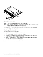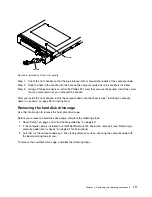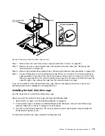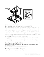
Filler
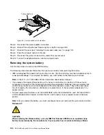
Figure 34. Filler installation
Step 5.
Reinstall the cover (see “Installing the compute node cover” on page 107).
Step 6.
Slide the compute node into the rack.
Step 7.
Reconnect the power cords and any cables that you removed.
Step 8.
Turn on the peripheral devices and the compute node.
Removing the front handle
Use this information to remove the front handle.
Before you remove the front handle, complete the following steps:
1. Read “Safety” on page v and “Installation guidelines” on page 89.
2. If the compute node is installed in an IBM NeXtScale n1200 Enclosure, remove it (see “Removing a
compute node from a chassis” on page 92 for instructions).
3. Carefully lay the compute node on a flat, static-protective surface with the cover side down, orienting
the compute node with the bezel pointing toward you.
To remove the front handle, complete the following steps.
Removing and replacing components
115
Summary of Contents for NeXtScale nx360 M4
Page 1: ...IBM NeXtScale nx360 M4 Installation and Service Guide Machine Type 5455 ...
Page 6: ...iv IBM NeXtScale nx360 M4 Installation and Service Guide ...
Page 34: ...20 IBM NeXtScale nx360 M4 Installation and Service Guide ...
Page 58: ...44 IBM NeXtScale nx360 M4 Installation and Service Guide ...
Page 94: ...80 IBM NeXtScale nx360 M4 Installation and Service Guide ...
Page 192: ...178 IBM NeXtScale nx360 M4 Installation and Service Guide ...
Page 538: ...524 IBM NeXtScale nx360 M4 Installation and Service Guide ...
Page 562: ...548 IBM NeXtScale nx360 M4 Installation and Service Guide ...
Page 722: ......
Page 730: ......
Page 737: ......
Page 738: ...Part Number 00KC216 Printed in China 1P P N 00KC216 1P00KC216 ...

