User Manual Of EL7-EC** AC Servo
35
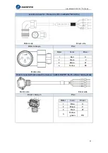
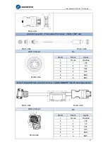
Direct connector CABLE-RZH*M*-114-TS Winding cable with holding brake
Motor side Driver side
Motor cable pin
Pin
Motor
Color
Driver
1
Blue
U
2
Black
V
3
Red
W
4
Yellow-
green
PE
A
Black
0V
B
Red
24V
Mechanical noise might exist when motor with holding brake is in operation but it
doesn’t affect the functionality of the motor.
When the holding brake circuit is closed (holding brake deactivated), there might be
magnetic flux leakage. Please be aware to not use magnetic sensor around motor
with holding brake.
24V operating voltage for the holding brake has to be ensured to maintain the
functionality of the holding brake. Please consider the voltage dropped over lengthy
motor cables due to increase in cable resistance.
It is recommended to have an isolated switching power supply for the holding brake
to prevent malfunctioning of the holding brake in case of voltage drop.
If the motor is using a magnetic encoder, holding brake wires need to be
differentiated between positive and negative terminal to prevent interference to the
magnetic encoder due to wrong polarity. It might cause alarm, loss in encoder
accuracy or abnormal vibration, etc.
Motor with optical encoder has no such problem, so holding brake circuit can be
connected in anyway.
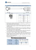
Table 2-7 Holding brake terminal pins in color codes
Motor flange
80 or below
Color
Brown Blue Red Black
Terminal
24V
0V
24V
0V
Pin
1
2
6
5
Motor flange
130 or above
Color
Red
Black
Terminal
24V
0V
Pin
2
1


