User Manual Of EL7-EC** AC Servo
67
【
3
】
Pulse sequence
+
Directional symbol
1
0
or
2
90°phase
difference
2 phase pulse
(
Phase A
+
Phase
B
)
1
CW pulse sequence
+
CCW pulse
sequence
3
Pulse sequence
+
Directional symbol
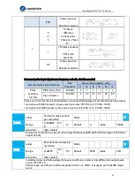
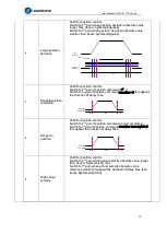
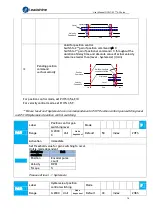
Command pulse input signal max. frequency and min. duration needed
Command pulse input interface
Max.
Frequency
Min. duration needed
(
μs
)
t1
t2
t3
t4
t5
t6
Pulse
sequence
interface
Differential drive
500 kHz
2
1
1
1
1
1
Open collector
200 kHz
5
2.5 2.5 2.5 2.5
2.5
Please set >0.1
μs for the duration between rising and falling edge of command pulse input signal.
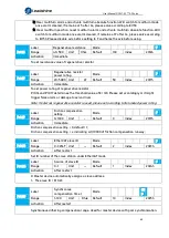
1 revolution with 2500 pulses 2-phase pulse input when Pr0.07=0 or 2, Pr0.08 = 10000;
1 revolution with 10000 pulses 1-phase pulse input when Pr0.07=1 or 3, Pr0.08 = 10000
Pr0.08
Label
Command pulse counts
per revolution
Mode
F
Range
0~838860
8
Uni
t
P-
Default
0
Index
2008h
Activation
After restart
Pulses per revolution can be set using object dictionary 608F, 6091, 6092. However, Pr0.08 has
higher priority.
Pr0.11
Label
Encoder pulse output per
revolution
Mode
F
Range
0~65535
Uni
t
P/r
Default
2500
Index
2011
Activation
After restart
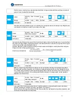
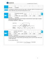
Including rising and falling edge of phase A and B, so encoder actual differential output pulse
count = Pr0.011 x 4
Please make sure: Motor rotational speed x Pr0.11 x 4
≤
1MHz. If exceeds, alarm Er280 might
occur.


