User Manual Of EL7-EC** AC Servo
168
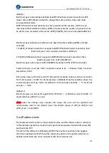
××××,××××,×00×,0111
Quick stop active
××××,××××,×0××,1111
Fault reaction active
××××,××××,×0××,1000
Fault
× is not affected by this bit state
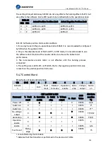
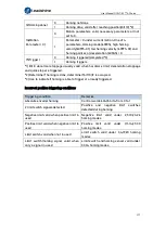
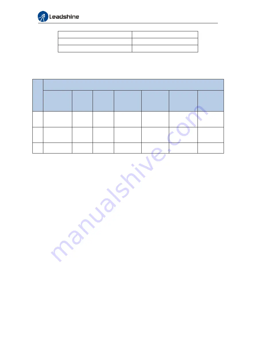
The definition of bit 8 and bit 13~12 in different operation modes are shown in the
following table
Bit
Operation Mode
Profile
Position
(PP)
Profile
Velocity
(PV)
Profile
Torque
(PT)
Homing
(HM)
Cyclic
Sync
Position
(CSP)
Cyclic Sync
Velocity
(CSV)
Cyclic
Sync
Torque
(CST)
13
Position
error is too
large
-
-
Homing
Process
error
-
-
-
12
-
Velocity
is 0
-
Homing
Process
completed
Following
valid
Following
valid
Following
valid
8
Abnormal
stop
-
-
Abnormal
stop
Abnormal
stop
-
-
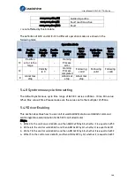
5.4.8 Synchronous cycle time setting
The default synchronous cycle time range of EL7-EC series is 250us – 10ms. Min value:
125us; Max value: 20ms. Please make sure the values set is the multiplier of 250us.
5.4.9 Driver Enabling
This section describes how to use control words 6040h/ status word 6041h command
switching/status determination forEL7-EC controlled motor.
Steps
:
1
:
Write 0 to the control word 6040h, and then AND 0x250 by bit, whether it is equal to 0x250
2
:
Write 6 to the control word 6040h, and then AND 0x231 by bit, whether it is equal to 0x231
3
:
Write 7 to the control word 6040h, and then AND 0x233 by bit, whether it is equal to 0x233
4
:
Write 15 to the control word 6040h, and then AND 0x237 by bit, whether it is equal to 0x237

