User Manual Of EL7-EC** AC Servo
163
5.4 Common Functions for All Modes
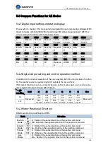
5.4.1 Digital input setting and status display
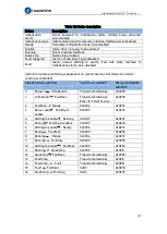
Please refer to chapter 5 for more details on digital I/O input and polarity settings.60FDh
object complies with IEC61800-200 standard input I/O status mapping object. 60FDh is
set according to function as the table below shows.
Bit31
Bit30
Bit29
Bit28
Bit27
Bit26
Bit25
Bit24
Z
signal
Reserve
d
Reserve
d
Reserve
d
Touch
Probe 2
Touch
Probe 1
BRAK
E
INP/V-COI
N /TLC
Bit23
Bit22
Bit21
Bit20
Bit19
Bit18
Bit17
Bit16
E-STO
P
Reserve
d
Reserve
d
Reserve
d
Reserve
d
Reserve
d
DI14
DI13
Bit15
Bit14
Bit13
Bit12
Bit11
Bit10
Bit9
Bit8
DI12
DI11
DI10
DI9
DI8
DI7
DI6
DI5
Bit7
Bit6
Bit5
Bit4
Bit3
Bit2
Bit1
Bit0
DI4
DI3
DI2
DI1
Reserve
d
HOME
POT
NOT
5.4.2 Digital output setting and control operation method
In addition to the internal operation of the servo system, EL7-EC also provides a function
for the master device to operate digital I/O output of the servo driver.
If I/O output function is set up as master device control, master device can control servo
driver digital I/O output through 60FEh object
Bit
Sub-index
31~21
21
20
19
18
17
16
15~0
01h
Reserved
DO6
valid
DO5
valid
DO4
valid
DO3
valid
DO2
valid
DO1
valid
Reserved
02h
DO6
enabled
DO5
enabled
DO4
enabled
DO3
enabled
DO2
enabled
DO1
enabled
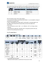
5.4.3 Motor Rotational Direction
Rotational direction is defined in 607Eh.
Mode
Set value
Position
Mode
PP 0
:
Rotate in the same direction as the position command
128
:
Rotate in the opposite direction to the position command
HM
CSP
Velocity
Mode
PV 0
:
Rotate in the same direction as the position command
64
:
Rotate in the opposite direction to the position command
CSV
Torque
Mode
PT 0
:
Rotate in the same direction as the position command
32
:
Rotate in the opposite direction to the position command
CST
ALL
Modes
0
:
Rotate in the same direction as the position command
224
:
Rotate in the opposite direction to the position command

