


6 | Function description
Working with the HR 600/2 unit
ð
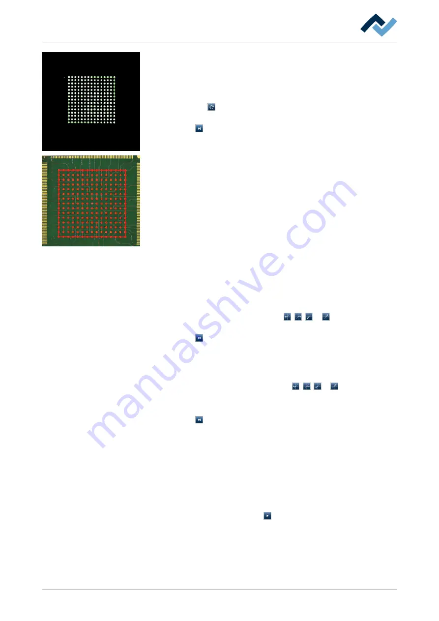
The lower camera detects the connections of the component with differ-
ent brightness degrees. The connections of the component are shown with
a coloured border.
ð
The process is stopped. If not all connections are recognized:
e) Select a suitable component from the component filter and apply it once more
with the button . If the component connectors are not properly detected,
click this button several times to improve detection.
f) Click on the button to proceed to the next step.
ð
The component is lifted and if necessary aligned. The connections will then
be detected again. The overlay is displayed. The overlay shown indicates
the correct position of the component on the PCB.
ð
The process is stopped. You can now select one of three overlay modes by
repeatedly pressing the <F4> key, and change the overlay colour via the
<F5> key. To do this, check if the overlay is correctly placed.
Notes:
– To change transparency, you can also move the slider.
The function keys of the keyboard are assigned as follows:
– <F4> To call up three different component display modes in the overlay.
– <F5> To change overlay colours
– <F6> To show a red frame
– <F8> To recalculate component position
If the overlay is not correct:
a) Move the camera head by clicking on the , , or buttons until the
overlay is correct.
b) Click on the button to proceed to the next step.
ð
The pick-and-place nozzle places the component in the target position.
ð
The process is stopped. The upper camera is switched on.
ð
If you want to check the positioning result:
c) Move the camera by clicking on the buttons , , or until the posi-
tioned component is displayed.
d) Check in the camera the results of the placement process.
e) Click on the button to proceed to the next step.
Version 2: Automatic mode:
In this mode, the entire placement process is carried out automatically. To do so,
you must select and enable a profile with a saved [Target position]. In any event, in
the short process pause time between single steps you have the opportunity to
stop the process and intervene.
ü
To start the placement process in automatic mode:
a) In the function selection field, enable the tab [Placement].
b) In the automation bar, click on the button.
ð
The automatic mode is started.
ð
The camera head is moved to the target position saved in the profile.
ð
The picture of the target position is saved.
ð
The head moves to the glass plate.
Ersa GmbH
3BA00207_01 Operating Instructions HR 600_2 | Rev. 3
136 / 169


