Program P6: Patch Panel 6-1: Patch Panel
299
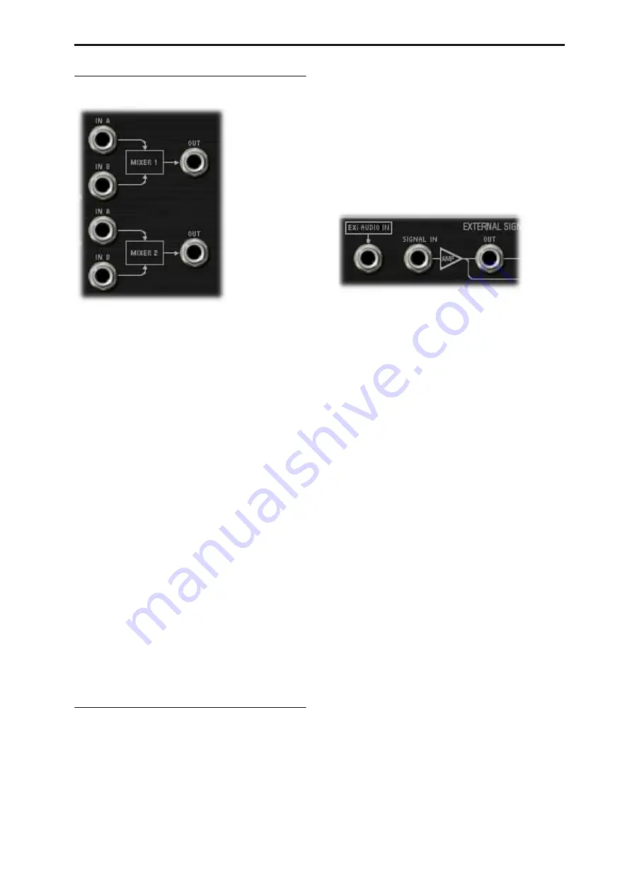
6–1j: MIXERS 1 and 2
MIXER 1
This is a simple 2-in, 1-out mixer; you can use it for
merging and scaling either control or audio signals.
Note that you can also use this to invert the polarity of
a signal.
The levels of inputs A and B are controlled by knobs on
the MG, EGs, and Modulation page, and can be
modulated via AMS; for more information, see “5-1g:
Mixers” on page 292.
IN A jack
This is the first input to the mixer.
IN B jack
This is the second input to the mixer.
OUT jack
This is the merged output of
IN A
and
IN B
.
MIXER 2
This is a second 2-in, 1-out mixer, identical to “MIXER
1,” above.
IN A jack
This is the first input to the mixer.
IN B jack
This is the second input to the mixer.
OUT jack
This is the merged output of
IN A
and
IN B
.
6–1k: EXTERNAL SIGNAL PROCESSOR
(ESP)
Important: the ESP is only active when
notes are played
The ESP can process live audio inputs, feedback from
effects, or any other audio from within the OASYS–as
well as audio from within the MS-20EX itself. Note,
however, that the ESP is only active when a voice is
being played on the MS-20EX.
It’s easy to make a patch in which only the incoming
audio is heard, with the built-in VCOs completely
silent–but you still need to press a key (or play a note
via MIDI) in order to activate the MS-20EX. You can
use the Program Hold parameter to keep the note
“held down” indefinitely, if you like.
For more information, see “Using the External Signal
Processor (ESP)” on page 301, and “Tip: Creating self-
triggering patches” on page 295.
Audio Inputs
EX
i
AUDIO IN jack
This mono input lets you route audio from elsewhere
in OASYS through the MS-20EX. You can use any of
the audio inputs, any of the audio outputs, the REC
buses, the FX Control buses, or the outputs of any of
the Insert, Master, or Total Effects.
You can also route live or recorded audio through the
MS-20EX, in realtime–and we’re sure that you’ll be
able to think of other creative uses!
The audio input source and channel (left, right, or L+R
summation) are selected by the Input Source and
Channel parameters in the current Program,
Combination Timbre, or Song Track.
For more information, see “4–2: EXi Audio Input” on
page 162 (Program mode), “2–6: EXi Audio Input” on
page 367 (Combination mode), and “2-6: EXi Audio
Input” on page 475 (Sequencer mode).
Once you’ve selected the desired audio source, you can
connect the
EX
i
AUDIO IN
jack to any input on the
Patch Panel. For instance, you can route the audio
through the HPF, LPF, or BPF, mix it with the built-in
VCOs and noise generator, and so on. You can also use
the ESP to convert the audio to a trigger or CV source,
as described under “Using the External Signal
Processor (ESP),” on page 301.
The
EX
i
AUDIO IN
is monophonic, but you can use
two MS-20EX together to process stereo signals:
1. Create a double EX
i
Program, and assign both
EX
i
1 and EX
i
2 to use the MS-20EX.
2. In the EX
i
Audio Input parameters, assign the left
channel to EX
i
1, and the right channel to EX
i
2.
3. Pan the output of EX
i
1 to the left, and the output
of EX
i
2 to the right.
NOTE
: In the Legacy MS-20 plug-in, the audio input is
normalled to the HPF’s Ext Signal Input. To enable
more flexibility in patching, this signal is
not
normalled
in the MS-20EX. When converting sounds from the
Legacy plug-in, the EX
i
audio input should be patched
to the Ext Signal In jack.
Summary of Contents for Electronic Keyboard
Page 1: ...Parameter Guide Parameter Guide ...
Page 2: ......
Page 180: ...Program mode EXi 170 ...
Page 290: ...EXi STR 1 Plucked String 280 ...
Page 572: ...Sequencer mode 562 ...
Page 700: ...Global mode 690 ...
Page 751: ...Insert Effects IFX1 IFX12 Routing 741 Fig 2 3a Fig 2 3b ...
Page 902: ...Effect Guide 892 ...


