8 Special procedures
147
of the CPU board has changed).
9.
Verify that the version of the firmware matches the one
listed for "Ceph FW" and "Ceph Core" in the release
package's versions.txt file using command:
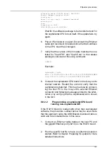
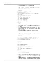
login
Example:
ngeoceph> login
main 1.4.4693/2012-08-10T15:32:43/TUULTESKELINEN
core 2012-01-31T12:17:34/EP2C70F672C6/AUTO
10. Connect the cephalostat CPU board to the X-ray unit's
internal network. Restart the unit and verify that the
cephalostat is detected. This may be done by connect-
ing the host PC to the X-ray unit's external Ethernet
connector and following messages printed to the s2ter-
minal or by verifying that the cephalostat tab is shown
in the GUI.
8.10 Troubleshooting
8.10.1
Problem: No connection to the X-ray
unit / R3220 circuit board
Indication
: A connection cannot be established. "Login fail
(no connection)" is continuously printed in the s2terminal.
Possible reasons and solutions
:
1.
No physical connection to between the host PC and the
X-ray unit. Check the link led next to the Ethernet port
is lit. Check that the cable is not faulty and that the CPU
board is powered.
2.
Incorrect network settings. Check that the IP and sub-
net mask is correctly set in the host PC. Check that the
X-ray unit's IP matches the IP you are trying to connect
to. Refer to chapter Preparing for update for further in-
structions.
3.
The Ethernet connector is connected to the wrong
Ethernet port on the R3220 board. Connect to the cor-
rect port: J3210.
4.
A software update has failed and left the CPU board in
a non-responsive state. Perform a volatile installation
as described in chapter Volatile installation.
The MAC address of the CPU board has changed due to a
different type of software component being loaded.
Disconnect and reconnect the Ethernet connector to have
Summary of Contents for ORTHOPANTOMOGRAPH OP 3D Pro
Page 2: ......
Page 4: ......
Page 8: ...iv rev...
Page 18: ...1 Introduction 10...
Page 27: ...2 Unit description 19 2 6 Unit movements Panoramic unit movements R C J D...
Page 29: ...2 Unit description 21...
Page 30: ...2 Unit description 22...
Page 38: ...4 PC requirements 30...
Page 54: ...5 Installing the unit 46 4 Fasten the covers...
Page 67: ...5 Installing the unit 59 C C D D Top cover of the column E E...
Page 104: ...7 Cephalometric calibration and alignment 96...
Page 111: ...7 Cephalometric calibration and alignment 103 3 Tighten the locking nut...
Page 117: ...7 Cephalometric calibration and alignment 109...
Page 128: ...8 Special procedures 120 6 Remove the arm from the column 4 nuts 7 Disassemble the arm...
Page 132: ...8 Special procedures 124 right handed assembly Prism assembly for the left handed cephalostat...
Page 158: ...8 Special procedures 150...
Page 165: ...9 OP 3D Pro Pre sales check list 157 9 11 Notes comments...
Page 166: ...9 OP 3D Pro Pre sales check list 158 9 12 Dimensions 463...
Page 167: ...9 OP 3D Pro Pre sales check list 159 9 13 Dimensions with cephalostat...


