3 Pre-installation requirements
24
■
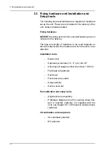
Make sure that the fixing hardware and wall can
withstand pull-out strengths of at least 5000 N.
NOTICE! Mounting bolts for floor and wall fastening are not
included in the delivery. The fixing hardware used to
permanently attach the unit to the wall must be correct type
for the wall and wall material.
■
Wall material should be suitable for fixing the unit.
If the wall is made of weak material, you may have
to use a reinforcing plate on the rear side of the wall
to hold the fixing hardware.
■
It is recommended for the installation site to have
supply mains over-current releases:
100-120V: 20A
220-240V: 15A
■
The place where the unit is to be installed and the
position from where the user takes exposures must
be correctly shielded from the radiation that is gen-
erated when the unit is operated. Follow the local
radiation and safety requirements.
■
Do not install the unit in environments where there
are corrosive or explosive vapours.
■
Special steps regarding EMC need to be taken
when installing the unit. For more information refer
to the EMC declaration in user's manual.
■
The unit must be installed at least 1.85m (73 in)
away from any non-medical electrical or electrome-
chanical equipment.
■
Mains extension cables MUST NOT be used with
the unit.
■
Maximum allowed mains line impedance is
0.2 ohms.
Summary of Contents for ORTHOPANTOMOGRAPH OP 3D Pro
Page 2: ......
Page 4: ......
Page 8: ...iv rev...
Page 18: ...1 Introduction 10...
Page 27: ...2 Unit description 19 2 6 Unit movements Panoramic unit movements R C J D...
Page 29: ...2 Unit description 21...
Page 30: ...2 Unit description 22...
Page 38: ...4 PC requirements 30...
Page 54: ...5 Installing the unit 46 4 Fasten the covers...
Page 67: ...5 Installing the unit 59 C C D D Top cover of the column E E...
Page 104: ...7 Cephalometric calibration and alignment 96...
Page 111: ...7 Cephalometric calibration and alignment 103 3 Tighten the locking nut...
Page 117: ...7 Cephalometric calibration and alignment 109...
Page 128: ...8 Special procedures 120 6 Remove the arm from the column 4 nuts 7 Disassemble the arm...
Page 132: ...8 Special procedures 124 right handed assembly Prism assembly for the left handed cephalostat...
Page 158: ...8 Special procedures 150...
Page 165: ...9 OP 3D Pro Pre sales check list 157 9 11 Notes comments...
Page 166: ...9 OP 3D Pro Pre sales check list 158 9 12 Dimensions 463...
Page 167: ...9 OP 3D Pro Pre sales check list 159 9 13 Dimensions with cephalostat...


