6 Panoramic and 3D calibrations and adjustments
80
6. Remove the mirror plate and the knob of the FH-laser.
Adjust four lasers from bottom to up.
Adjust the lowest laser first. Loosen the upper screw. The
laser starts to rotate. Align the laser horizontally. Tighten
the screw.
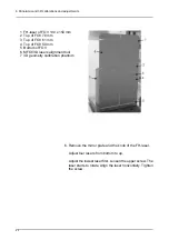
1 FH-laser of FOV 130 x 150 mm
2 Top of FOV 78 mm
3 Top of FOV 61 mm
4 Top of FOV 50 mm
5 Bottom of FOV
6 MFOV3D lasers alignment tool
7 3D geometry calibration phantom
Summary of Contents for ORTHOPANTOMOGRAPH OP 3D Pro
Page 2: ......
Page 4: ......
Page 8: ...iv rev...
Page 18: ...1 Introduction 10...
Page 27: ...2 Unit description 19 2 6 Unit movements Panoramic unit movements R C J D...
Page 29: ...2 Unit description 21...
Page 30: ...2 Unit description 22...
Page 38: ...4 PC requirements 30...
Page 54: ...5 Installing the unit 46 4 Fasten the covers...
Page 67: ...5 Installing the unit 59 C C D D Top cover of the column E E...
Page 104: ...7 Cephalometric calibration and alignment 96...
Page 111: ...7 Cephalometric calibration and alignment 103 3 Tighten the locking nut...
Page 117: ...7 Cephalometric calibration and alignment 109...
Page 128: ...8 Special procedures 120 6 Remove the arm from the column 4 nuts 7 Disassemble the arm...
Page 132: ...8 Special procedures 124 right handed assembly Prism assembly for the left handed cephalostat...
Page 158: ...8 Special procedures 150...
Page 165: ...9 OP 3D Pro Pre sales check list 157 9 11 Notes comments...
Page 166: ...9 OP 3D Pro Pre sales check list 158 9 12 Dimensions 463...
Page 167: ...9 OP 3D Pro Pre sales check list 159 9 13 Dimensions with cephalostat...


