J4350 and J6350 Services Router Getting Started Guide
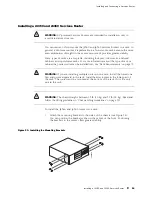
Chassis Grounding
To meet safety and electromagnetic interference (EMI) requirements and to
ensure proper operation, the Services Router must be adequately grounded
before power is connected. In addition to the grounding pin on the AC power
plug cord, a threaded insert (PEM nut), screw, and washer are provided on
the rear of the chassis to connect the router to earth ground.
CAUTION:
Before router installation begins, a licensed electrician must attach a
cable lug to the grounding and power cables that you supply. A cable with an
incorrectly attached lug can damage the router (for example, by causing a short
circuit).
The grounding cables must be 14 AWG single-strand wire cable, and
must be able to handle amperage up to 20 A.
Each grounding lug must be a ring-type, vinyl-insulated TV14-6R lug, or
equivalent, to accommodate the 14 AWG cable.
To ground the router before connecting power, you connect the grounding cable
to earth ground and then attach the lug on the cable to the chassis grounding
point, with the screw. (See “Connecting Power” on page 86.)
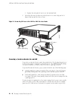
Connecting Power
J4350 Services Routers have a single fixed power supply. J6350 Services
Routers have one or two field-replaceable power supplies. For more
information about the J-series power specifications, see “Power Guidelines,
Requirements, and Specifications” on page 74.
WARNING:
DC-powered Services Routers are intended for installation only in
a restricted access location.
Connecting AC Power
The router must be connected to earth ground during normal operation. The
protective earthing terminal on the rear of the chassis is provided to connect
the router to ground. Additional grounding is provided to an AC-powered router
when you plug its power supply into a grounded AC power receptacle.
The AC power cord shipped with the router connects the router to earth ground
when plugged into an AC grounding-type power outlet. The router must be
connected to earth ground during normal operation.
86
Connecting Power
Summary of Contents for J4350
Page 14: ...J4350 and J6350 Services Router Getting Started Guide xiv Table of Contents...
Page 22: ...2 J series Overview...
Page 68: ...J4350 and J6350 Services Router Getting Started Guide 48 Field Replaceable PIMs...
Page 75: ...Services Router User Interface Overview Figure 25 J Web Layout Using the J Web Interface 55...
Page 88: ...J4350 and J6350 Services Router Getting Started Guide 68 Using the Command Line Interface...
Page 90: ...70 Installing a Services Router...
Page 100: ...J4350 and J6350 Services Router Getting Started Guide 80 Site Preparation Checklist...
Page 112: ...J4350 and J6350 Services Router Getting Started Guide 92 Powering a Services Router On and Off...
Page 144: ...J4350 and J6350 Services Router Getting Started Guide 124 Verifying Secure Web Access...
Page 162: ...142 Maintaining Services Router Hardware...
Page 194: ...J4350 and J6350 Services Router Getting Started Guide 174 Troubleshooting Hardware Components...
Page 204: ...184 J series Requirements and Specifications...
Page 220: ...J4350 and J6350 Services Router Getting Started Guide 200 ISDN RJ 45 Connector Pinout...
Page 267: ...Part 5 Index Index 247...
Page 268: ...248 Index...

