File Version: 1.2
29
/
37
JAKA MiniCab Hardware User Manual
When configured as DI, it is an NPN type input, and will be effective when UDIO_1(PIN13) is short-connected
to GND(PIN6). When using internal UDIO_24V, short connect PIN1 and PIN2 by default. The typical wiring
diagram is as follows:
K1
1
3
5
7
9
2
4
6
8
10
11
13
15
17
19
12
14
16
18
20
Figure 6-8 Wiring Diagram with UDIO_x as DI
2. DO Digital Output:
When configured as the digital output interface DO, it is NPN type output, which uses an Open Collector output
internally and is connected with a continuing current diode, which supports the output current capacity up to 1A .
When the internal UDIO_24V is applied, the typical wiring diagram is as follows:
1
3
5
7
9
2
4
6
8
10
11
13
15
17
19
12
14
16
18
20
LOAD
Figure 6-9 Wiring Diagram with UDIO_x as DO
3. Dual channel redundant security architecture
MiniCab isolates UDIO internally. When high safety performance is required, UDIO1 and UDIO2, UDIO3 and
UDIO4, UDIO5 and UDIO6 can be combined into three I/O pairs to ensure that MiniCab can detect relevant
signals in case of emergency.
6.3
Braking Voltage Setting
The MiniCab has an integrated voltage brake circuit to relieve the EMF generated by the robot during
deceleration and braking. When the user uses the external power supply, it needs to be set to avoid
overvoltage protection which will cause power-off or damage to the controller. When setting the braking voltage,
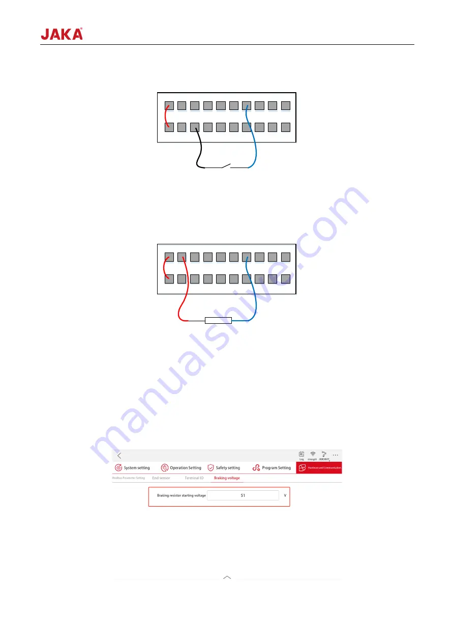
you need to power off the robot arm before operation. The setting path is as follows:


