item Controller BL 1-04 /C
― Product manual
36
PWM frequency f
PWM
*)
BL 1-04 /C
I
nenn
I
max
10 kHz
4 A
12 A
16 kHz
3 A
9 A
*) The PWM frequency is the reciprocal of half of the current controller cycle time ti. The variable cycle times enable particularly high dynamics combined with
reduced power data.
The maximum overload time is also subject to derating as a function of the rotational frequency (= rotational speed * number
of pole pairs). It begins with values below 2 Hz and is linear up to 0.
f
el
t
max
0
0,2 s
>= 2 Hz
2 s
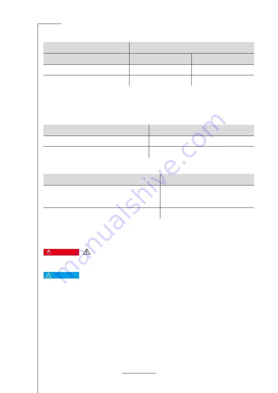
Motor cable requirements
Characteristic
Value
Cable length
l ≤ 25 m See section 9.1 Notes concerning the safe
and EMC-compliant installation on page 52
Cable capacity
C‘ ≤160 pF/m of one phase
Motor temperature monitoring system
Dangerous electrical voltage!
DANGER
Dangerous electrical voltage!
The signals for the temperature sensor "MT-" and "MT+" at the motor connector [X6] must be connected to protective ex
-
tra-low voltage (PELV) on the motor side and they must be insulated against the motor phases.
NOTICE
Electronic motor overload protection
The servo drive features electronic overload protection with thermal memory retention.
To ensure effective protection, the rated current and maximum current of the motor and the overload time (I2t time) must be
parametrised as described in the product manual.


