item Controller BL 1-04 /C
― Product manual
58
An existing holding brake in the motor must be connected to the terminals BR+ and BR-. Please note the maximum output
current that is provided by the servo drive.
DANGER
Dangerous electrical voltage!
The signals for the temperature sensor "MT-" and "MT+" at the motor connector [X6] must be connected to protective ex
-
tra-low voltage (PELV) on the motor side and they must be insulated against the motor phases.
WARNING
Risk of injury
The brake output of the servo drive (BR+, BR-) must not be used as the sole stop element in safety-oriented applications.
NOTICE
Risk of destruction due to the mix-up of connectors
The servo drive may be irreparably damaged if the connectors for the motor [X6] and supply [X9] are mixed up.
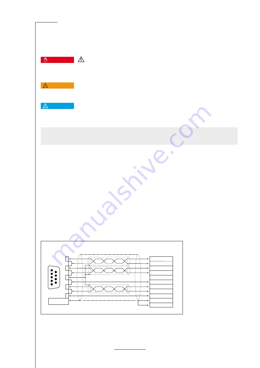
9.5 Connector: resolvers/analogue Hall encoders [X2A]
Two different encoder types can be connected to the 9-pin D-Sub connector:
▪ Resolvers
▪ Analogue Hall generators with tracks that are offset by 90° (sine/cosine)
Diverging from the analogue evaluation via the X2B interface, this input has a higher resolution and it is possible to read in
higher amplitudes.
Configuration on the device [X2A]
D-SUB connector, 9-pin type, female
Mating connector [X2A]
▪ D-SUB connector, 9-pin type, male
▪ Housing for a 9-pin D-SUB connector with locking screws of type 4/40 UNC
Pin assignment [X2A]
S2 / SIN +
MT -
R1 / C
Cable shield (optional)
Connector housing
S4 / SIN -
S1 / COS +
S3 / COS -
MT +
R2 / Carrier -
Resolver output
at the Motor
D-SUB connector
Connector housing
male
1
6
5
9
1
2
6
5
9
4
8
3
7
Abbildung 24: Pin assignment: resolver connector [X2A]


