background image

Vortex86DX-MSJK Windows Embedded CE 6.0 R3 Jump Start Rev 2.0


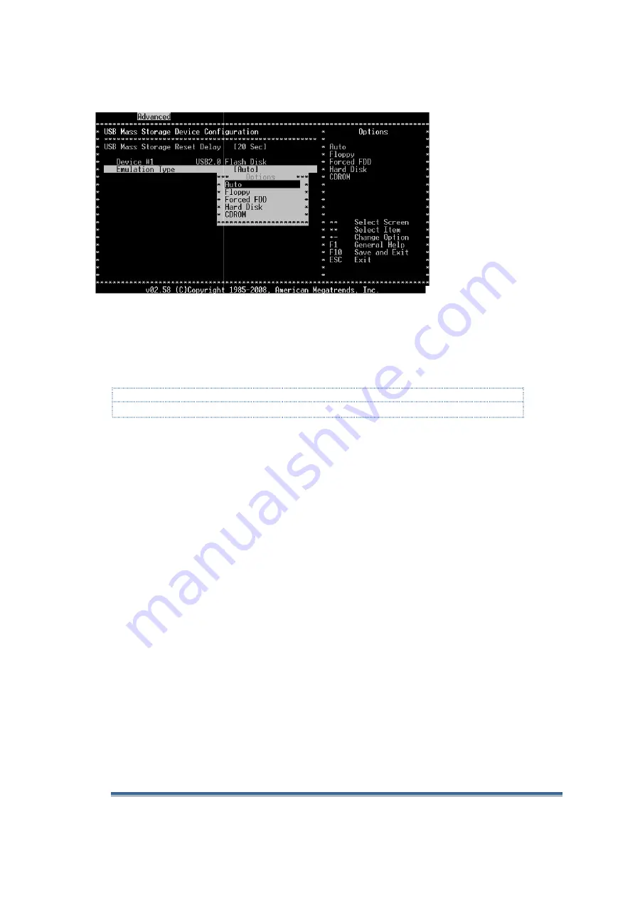
Figure J-4  

The “Device #1” setting list the detected USB flash storage device.  The device name listed will be 
different for each different type of USB flash storage from

The default Emulation Type is set to “Auto”, which works for some device and does not work for 
some device. 

Note:  

You may have to go through multiple tries to find a setting that work

For most USB flash storage device, setting the 

Boot Device Priority

In addition to configuring the USB flash storage device emulation type, the device boot sequence 
also affect the VDX-6326 SBC

Press the “Esc” key to go back to the p
step back to the main BIOS settings menu.

From the main BIOS setting menu, use the Left/Right arrow key to move to the Boot setting menu.

From the Boot Settings menu, use the Up/Down arrow key to na
option and press enter to bring up the Boot Device Prior


Vortex86DX-MSJK CE 6.0 Jump Start 

MSJK Windows Embedded CE 6.0 R3 Jump Start Rev 2.0 


The “Device #1” setting list the detected USB flash storage device.  The device name listed will be 
different for each different type of USB flash storage from different company.

The default Emulation Type is set to “Auto”, which works for some device and does not work for 

You may have to go through multiple tries to find a setting that work.  

For most USB flash storage device, setting the Emulation Type to “Hard Disk” yield the best result. 

Boot Device Priority 

In addition to configuring the USB flash storage device emulation type, the device boot sequence 

6326 SBC’s boot process. 

Press the “Esc” key to go back to the previous menu.  You need to press the “Esc” a few times to 

back to the main BIOS settings menu. 

From the main BIOS setting menu, use the Left/Right arrow key to move to the Boot setting menu.

From the Boot Settings menu, use the Up/Down arrow key to navigate to the Boot Device Priority 
option and press enter to bring up the Boot Device Priority screen, as shown in Figure J

MSJK CE 6.0 Jump Start - Getting Started Guide 

Page 129 

The “Device #1” setting list the detected USB flash storage device.  The device name listed will be 

different company. 

The default Emulation Type is set to “Auto”, which works for some device and does not work for 

Emulation Type to “Hard Disk” yield the best result.  

In addition to configuring the USB flash storage device emulation type, the device boot sequence 

ress the “Esc” a few times to 

From the main BIOS setting menu, use the Left/Right arrow key to move to the Boot setting menu. 

vigate to the Boot Device Priority 

ity screen, as shown in Figure J-5. 

Summary of Contents for Vortex86DX-MSJK

Page 1: ...Vortex86DX MSJK Windows Embedded CE 6 0 R3 Jump Start Kit Getting Started Guide Samuel Phung Windows Embedded MVP ICOP Technology Inc...

Page 2: ...15 Ethernet Connectivity 15 CE 6 0 OS Runtime Image Development OS Design 15 CE 6 0 Application Development with Visual Studio 15 Serial Port Connectivity 15 Development Environment Setup with DHCP 1...

Page 3: ...ing 39 The Build Process Completed 39 Part 7 Download CE 6 0 OS Runtime to Target Device 41 Target Device Preparation 41 Configure Target Device Connectivity Options 42 Add New Target Device Profile 4...

Page 4: ...79 Create a New Managed Code Application Project 79 Add Codes and Build the Application Project 81 Preparing Target Device to Connect to VS2008 IDE 82 Configure VS2008 Device Connectivity Settings 82...

Page 5: ...DiskPrep 120 Appendix I CoreCon Connectivity 123 Appendix J Recover Jump Start Kit s Original Files 125 Vortex86DX MSJK Preconfigured Files 125 Recover Damaged Files 125 Preparing USB Flash Storage t...

Page 6: ...ile it s possible to use the emulator or VirtualPC as the target device and work through similar exercises a real hardware provides a more practical learning environment The VDX 6326 single board comp...

Page 7: ...lso included an Ethernet bootloader needed to support custom OS development to download OS runtime image from the development workstation to the target device One RJ 45 Ethernet Crossover cable With a...

Page 8: ...of 144 VDX 6326 SBC Board Support Package BSP for CE 6 0 VDX 6326 SDK for CE 6 0 CoreCon component for CE 6 0 AutoLaunch component for CE 6 0 Sample project codes for the exercises in this guide Note...

Page 9: ...otocols and services In addition to improvement to the OS and development tool the CE 6 0 R3 release added the following components Silverlight for Windows Embedded Flash Lite Browser plug in to rende...

Page 10: ...5 is a popular developer friendly development tool to develop broad range of applications that can run on different version of the Windows operating system Using the VS2005 IDE developer is able to cr...

Page 11: ...ng the VS2005 IDE Develop Managed code application with Visual Basic using the VS2005 IDE Develop Native code application with Visual C using the VS2008 IDE Develop Managed code application with Visua...

Page 12: ...O dll To access the 16 bit GPIOs IO dll To access the VDX 6326 SBC s hardware I O WDT dll To access the Watchdog timers When developing an OS design with the ICOP_VDX6326_60B BSP these DLLs are includ...

Page 13: ...figuration settings fonts etc The OS design is made up by a group of components Catalog The component catalog lists all of the components provided by Platform Builder and installed 3 rd party componen...

Page 14: ...igure the OS design to generate runtime image supporting 256MB of RAM PRJ_ENABLE_FSREGHIVE Configure the OS design to enable Hive based registry support _WINCEROOT Defines the root directory for the C...

Page 15: ...ce for testing and debug CE 6 0 Application Development with Visual Studio Both Visual Studio 2005 and 2008 support CE 6 0 managed and native code application development and able to deploy applicatio...

Page 16: ...the connection DHCP service for the target device needs to be enabled on your network Some secured network may require the target device s MAC address to be added to the authorized device list to be...

Page 17: ...work without DHCP Direct Connection using Cross Over RJ 45 Ethernet Cable Connectivity can be established by attaching the target device to the development workstation directly using a cross over RJ 4...

Page 18: ...4c96 b39d 37baf6b5b1dc DisplayLang en Visual Studio 2005 SP1 update for Vista If you are using a Windows XP workstation skip this step If you have the full retail or evaluation version of Windows Embe...

Page 19: ...jump start kit CD in the Software folder Windows Embedded CE 6 0 Installation Since the CE 6 0 development tool Platform Builder is a plug in to the VS2005 IDE the VS2005 development tool must be inst...

Page 20: ...www microsoft com downloads details aspx FamilyID f41fc7c1 f0f4 4fd6 9366 b61e0ab59565 DisplayLang en Windows Embedded CE 6 0 R3 Installation After installing the CE 6 0 R2 install the CE 6 0 R3 updat...

Page 21: ...ile format AutoLaunch_v200_x86_WinCE600 msi is provided with the jump start kit CD To install locate and launch this component on the jump start CD in the Software directory Software AutoLaunch_v200_x...

Page 22: ...tion for this getting started guide the Visual Studio IDE is resized to 800x600 and may have different looks and feel from the VS2005 IDE launch in full screen mode with 1024x768 and higher display re...

Page 23: ...OS design project Make sure the Create directory for solution check box is checked Click on the OK button to continue Windows Embedded CE 6 0 OS Design Wizard When a new CE 6 0 OS design project is se...

Page 24: ...led BSPs including BSPs from third party companies are listed as shown in Figure 9 Fig 9 OS design Wizard Select BSP From the Available BSPs pane select ICOP_VDX6326_60B x86 BSP Click on the Next butt...

Page 25: ...rd Design Template Variants From the Design Template Variants screen select the Internet Appliance option Continue and click on the Next button to bring up the Application Media selection screen OS De...

Page 26: ...ation selection screen Note NET Compact Framework is needed to support managed code application In this step the NET Compact Framework 2 0 library is excluded In the later step we will add the newer v...

Page 27: ...curity warning is raised to warn one or more of the selected components for the OS design may pose security risk as shown in Figure 15 Fig 15 Catalog Item Notification Security Warning Click on the Ac...

Page 28: ...ports different project types A solution provides a centralized work space to keep different project types supporting the same solution in one location For example the MyWinCE solution may include the...

Page 29: ...ded to the OS design as the result of being a dependency to another component selected for the OS design Work through the following steps to further customize the MyWinCE OS design project From the VS...

Page 30: ...erial port driver to the OS runtime to support COM1 the first serial port By default the VDX 6326 SBC s 1 st serial port is configured as follow COM1 IRQ 4 3F8h 2nd Serial Port Note This component set...

Page 31: ...eps NET Compact Framework 2 0 components were removed from the selection Expand the Core OS CEBASE Applications and Services Development node and select the following newer version of the NET Compact...

Page 32: ...5s 1388 Hex 5000 decimal Process1 Cerdisp exe c Launch Remote Display application Process1Delay dword 00002710 delay 5s 2710 Hex 10000 decimal From the Third Party RegFlushApp node select and include...

Page 33: ...design Note The Remote Display Application provides the function to access the CE 6 0 desktop remotely from the development workstation similar to the Remote Desktop feature for Windows XP The AutoLa...

Page 34: ...e OS design to generate the OS runtime image in release mode From the VS2005 IDE select Build Configuration Manager to bring up the Configuration Manager screen as shown in Figure 19 Fig 19 Configurat...

Page 35: ...esign The Registry The registry plays a key role in controlling how the CE 6 0 OS runtime behave loads driver application and more Improper registry entries can cause series problem and can prevent th...

Page 36: ...registry entries to the OS design to enable the FTP server and configure the AutoLaunch utility to launch CoreCon executable and Remote Display application From the VS2005 IDE click on the Solution E...

Page 37: ...pIp EnableDHCP dword 0 IpAddress multi_sz 192 168 2 233 Subnetmask multi_sz 255 255 255 0 Note When the KITL build option is enabled the CE 6 0 OS runtime image is generated with the VMINI driver to s...

Page 38: ...rial Port driver This driver is provided by the Platform Builder in the component catalog The Serial Port driver components in the ICOP_VDX6326_60B BSP when selected enable the appropriate environment...

Page 39: ...Process Starting From the VS2005 IDE select Build Build Solution to launch the build process Fig 22 VS2005 IDE showing the OS design being built Depending on the development workstation s processor sp...

Page 40: ...warnings are non critical and do not impact system function However as part of good engineering practice it s good to go through the warning messages to identify potential problem The resulting CE 6...

Page 41: ...appendix A and B for more information about connectivity for downloading OS runtime image from the development station to target device The exercises in this guide are created with both the developme...

Page 42: ...nt station to the target device we need to configure a target device connectivity profile and associate the profile to the target device VDX 6326 SBC in use In this section we will work through the st...

Page 43: ...n to add a new target device profile as shown in Figure 25 Fig 25 Target Device Connectivity Options Add new device Enter MyTargetDevice as the new target device name Click on the Add button to contin...

Page 44: ...Options screen continuing from previous section clicks on the top most Settings button to bring up the Ethernet Download Settings screen as shown in Figure 27 Fig 27 Ethernet Download Settings The Et...

Page 45: ...As Eboot bin launches it sends request to an available DHCP server to acquire IP address and broadcasts bootme messages to the development station to request and download OS runtime image After recei...

Page 46: ...onnectivity profile created and VDX 6326 SBC associated to this profile we are now ready to download the CE 6 0 OS runtime image from the development station to the VDX 6326 SBC From the VS2005 IDE se...

Page 47: ...cess As the image download takes place the Download Runtime Image to MyTargetDevice screen display download activities as shown in Figure 32 Note Once launched the Eboot bin Ethernet bootloader will c...

Page 48: ...NK bin needs to be copied to the local storage and configure with an appropriate bootloader The NK bin OS runtime image file in release mode is generated in the following directory C WINCE600 OSDesign...

Page 49: ...Project Add New SDK from the VS2005 IDE to bring up the SDK Property Pages screen as shown in Figure 34 Fig 34 New SDK Property Page Enter MyWinCE600_SDK as the name for the SDK Fill in the company n...

Page 50: ...ly button and then the OK button to complete configuring the new SDK To make changes to the SDK before compiling from the VS2005 IDE s Solution Explorer tab expand the SDKs folder right click on MyWin...

Page 51: ...library files generated during the OS design build process From VS2005 IDE select Build Build All SDKs to build and generate the installation package for the SDK After the build process is completed t...

Page 52: ...ate a New Native Code Application Project From the VS2005 IDE select File New Project to bring up the new project wizard as shown in Figure 38 Fig 38 New project wizard On the new project wizard scree...

Page 53: ...om the Selected SDKs pane on the right click to highlight the PocketPC 2003 entry Click on the single left pointing arrow located to the left of the Selected SDKs pane to remove the PocketPC 2003 entr...

Page 54: ...step as shown in Figure 42 Fig 42 Win32 smart device project wizard Project settings Keep the default selection to create a Windows application Click on the Finish button to complete the wizard and ge...

Page 55: ...ps to add some code to the VS2005_Win32_HelloWorld project From the VS2005 IDE s Solution Explorer tab double click on the VS2005_Win32_HelloWorld cpp file in the Source Files folder to view and edit...

Page 56: ...CPU architectures under the above directory Each of these folders contains CoreCon component files to support the corresponding CPU family These CoreCon files are copied to the development workstatio...

Page 57: ...CoreCon connectivity we need to know the CE 6 0 target device s IP address Work through the following steps to find out the IP address With CE 6 0 running on the target device from the CE 6 0 desktop...

Page 58: ...owing steps to configure the device connectivity settings From the VS2005 IDE select Tools Options to bring up the Options screen as shown in Figure 47 Fig 47 VS2005 Options Expand the Device Tools no...

Page 59: ...E600_SDK x86 Device Properties screen Click on the OK button to close the Options screen Establish Connectivity to CE 6 0 Target Device To initiate connectivity to the target device select Tools Conne...

Page 60: ...S2005_Win32_HelloWorld application to the target device From the VS2005 IDE select Debug Start Debugging to download the application to the target device As the VS2005_Win32_HelloWorld application dow...

Page 61: ...er Languages Visual C SmartDevice node and select WindowsCE as the project type On the right pane select Device Application Enter VS2005_CSharp_HelloWorld as the name of the project Enter C Lab as the...

Page 62: ...the text box at the center of the form Add a button to Form1 change the name to buttonHelloWorld change the caption to Hello World and place the button to the center of the form just below the textHel...

Page 63: ...tion exercise in Part 9 of this guide to establish the connection Configure VS2005 Device Connectivity Settings Managed code application can use the same native code application s CoreCon connectivity...

Page 64: ...elect MyWinCE600_SDK as shown in Figure 57 Fig 57 Connect to Device Platform selection From the Connect to Device screen click on the Connect button to establish connectivity to the target device Upon...

Page 65: ...9 VS2005_CSharp_HelloWorld managed code application running on target device Debug Application Running on Target Device In this section we will work through the steps to set break point and step throu...

Page 66: ...above breakpoint is set while the application is running on the target device With the breakpoint in place work through the following steps to execute the VS2005_CSharp_HelloWorld application and caus...

Page 67: ...ng on the target device is showing the Hello World message indicates the line of code just before the current breakpoint has been executed as shown in Figure 62 Fig 62 CE 6 0 application halt at the b...

Page 68: ...tion press the F5 key from the VS2005 IDE From the VS2005_CSharp_HelloWorld application screen running on the target device clicking on the Hello World button again will execute the code and cause the...

Page 69: ...ate a New Native Code Application Project From the VS2008 IDE select File New Project to bring up the new project wizard as shown in Figure 64 Fig 64 New project wizard On the new project wizard scree...

Page 70: ...Win32 smart device project wizard Platform SDK selection From the Selected SDKs pane on the right click to highlight the Windows Mobile 5 0 Pocket PC SDK entry Click on the single left pointing arrow...

Page 71: ...ed SDKs pane as shown in Figure 67 Fig 67 Win32 smart device project wizard Platform SDK selection Click on the Next button to bring up the Project Settings step as shown in Figure 68 Fig 68 Win32 sma...

Page 72: ...IDE with VS2008_Win32_HelloWorld project active Work through the following steps to add some code to the VS2008_Win32_HelloWorld project From the VS2008 IDE s Solution Explorer tab double click on th...

Page 73: ...orresponding to the CPU architectures under the above directory Each of these folders contains CoreCon component files to support the corresponding CPU family These CoreCon files are copied to the dev...

Page 74: ...CoreCon connectivity we need to know the CE 6 0 target device s IP address Work through the following steps to find out the IP address With CE 6 0 running on the target device from the CE 6 0 desktop...

Page 75: ...velopment workstation with the target device s IP address Work through the following steps to configure the device connectivity settings From the VS2008 IDE select Tools Options to bring up the Option...

Page 76: ...IP Transport screen select the Use specific IP address option and enter the target device s IP address from the earlier step Click on the OK button to close the Configure TCP IP Transport screen Click...

Page 77: ...cceeded Click on the Close button to close the Connecting screen Download Application to Target Device With CoreCon connectivity established between the VS2008 development workstation and CE 6 0 targe...

Page 78: ...6 0 R3 Jump Start Rev 2 2 Page 78 of 144 Fig 79 VS2008_Win32_HelloWorld running on the target device This concludes the exercise to create a CE 6 0 native code application using VS2008 and download t...

Page 79: ...nd the Visual C node and select Smart Device as the project type On the right pane select Smart Device Application Enter VS2008_CSharp_HelloWorld as the name of the project Enter C Lab as the location...

Page 80: ...roject wizard steps After the project wizard step is completed the initial VS2008_CSharp_HelloWorld project files are created in the following folder C Lab VS2008_CSharp_HelloWorld The initial applica...

Page 81: ...name to buttonHelloWorld change the caption to Hello World and place the button to the center of the form just below the textHelloWorld text box Double click on the Hello World button to bring up the...

Page 82: ...S2008 Managed code application can use the same native code application s CoreCon connectivity with the same device connectivity settings to establish connection between the development workstation an...

Page 83: ...the Connection succeeded message as shown in Figure 86 Fig 86 Connection succeeded Click on the Close button to close the Connecting screen Download Application to Target Device With CoreCon connecti...

Page 84: ...on downloaded and executed on the target device the application screen is shown on the CE 6 0 target device s desktop as shown in Figure 88 Fig 88 VS2008_CSharp_HelloWorld managed code application run...

Page 85: ...vigate to the buttonHelloWorld_Click event function Click on the following line of code and press the F9 key to set a breakpoint as shown in Figure 89 textHelloWorld Text 2nd Hello World Fig 89 VS2008...

Page 86: ...running on the target device is showing the Hello World message indicates the line of code just before the current breakpoint has been executed as shown in Figure 91 Fig 91 CE 6 0 application halt at...

Page 87: ...tion press the F5 key from the VS2008 IDE From the VS2008_CSharp_HelloWorld application screen running on the target device clicking on the Hello World button again will execute the code and cause the...

Page 88: ...d Options node to bring up the Build options selection window as shown in Figure 93 Fig 93 MyWinCE Property Pages Build options On the right pane select the Enable KITL no IMGNOKITL 1 option Click on...

Page 89: ...ious debug and troubleshooting resources available In the following section we will work through a series of exercise using remote tools from the VS2005 IDE to access the CE 6 0 OS runtime on the targ...

Page 90: ...lopment workstation select Connection Refresh to collect updated running process from the target device The ceplayer exe process will shows up in the the Process section Click to highlight the ceplaye...

Page 91: ...7 Remote Registry Editor To view which device drivers are loaded take a look at registry entries under the following registry key HKEY_LOCAL_MACHINE Drivers Active To exit and close the remote registr...

Page 92: ...Information tool From the VS2005 IDE select Target Remote Tools System Information to bring up the Select a Windows CE Device screen From the Select a Windows CE Device screen click on the Default De...

Page 93: ...to get start with CE 6 0 develop quickly There are advance subjects not covered in this guide which you need to pursue to further your knowledge Every embedded development project involves different h...

Page 94: ...B and PS 2 interfaces Connecting to Local Area Network with DHCP It s a typical setup to connect both the development workstation and the target device to a Local Area Network with DHCP service to pro...

Page 95: ...ial Debug Messages To capture serial debug messages from the target device a null RS 232 serial modem cable is connected between the target device s COM1 and an available serial port on the developmen...

Page 96: ...ded by the Platform Builder For the exercises in this guide the R6040 Ethernet interface is used The R6040 Ethernet interface is located on the back of the enclosure between the USB and PS 2 interface...

Page 97: ...registry entries to configure and build a CE 6 0 OS runtime with static IP address Capturing Serial Debug Messages To capture serial debug messages from the target device a null RS 232 serial modem ca...

Page 98: ...a built to the USB video class specification Phidgets USB I O driver shared source projects http www codeplex com PhidgetsWinCEDriver Phidgets are an easy to use set of building blocks for low cost se...

Page 99: ...px Windows Embedded CE How to and tutorials http msdn microsoft com en us windowsembedded ce aa731296 aspx Windows Embedded CE Learning Material from embeddedSPARK program http www microsoft com windo...

Page 100: ...oldered on 256MB DDR2 RAM provides sufficient system memory to support Windows Embedded CE Windows XP Embedded and WEPOS The 3 10 100Mbps Ethernet the 3 high bandwidth USB 2 0 ports the 4 serial ports...

Page 101: ...utomation point of sales information kiosk and other embedded devices By integrating key peripherals into a product quality design along with the support for the Windows Embedded technologies the VDX...

Page 102: ...1 x Type I II CF Slot 1 x PS 2 K B Mouse 3 x RS 232 1 x RS 232 422 485 1 x Parallel 1 x Mini PCI socket 1 x PC 104 expansion 1 x 16 bit GPIO Display Chipset XGI Z9s Display Memory 32MB DDR2 memory Dis...

Page 103: ...Vortex86DX MSJK Windows Embedded CE 6 0 R3 Jump Start Rev 2 2 Page 103 of 144 VDX 6326 SBC Connectors Jumpers and LED...

Page 104: ...in J18 PRINT Box Header 2 0 13x2 26 pin J19 COM4 Box Header 2 0 5x2 10 pin J20 FDD Pin Header 2 0 17x2 24 pin J25 PC104 Connector 64 pin Box Header 2 54 32x2 64 pin J26 PC104 Connector 40 pin Box Head...

Page 105: ...in Signal Name 1 DCD1 2 RXD1 3 TXD1 4 DTR1 5 GND 6 DSR1 7 RTS1 8 CTS1 9 RI1 10 GND 11 GND J11 GPIO Port 0 Port 1 PWMx16 J12 COM2 RS232 RS422 RS485 Change setting by BIOS Pin Signal Name Pin Signal Nam...

Page 106: ...T 4 PD2 17 SLIN 5 PD3 18 GND 6 PD4 19 GND 7 PD5 20 GND 8 PD6 21 GND 9 PD7 22 GND 10 ACK 23 GND 11 BUSY 24 GND 12 PE 25 GND 13 SLCT 26 NC J19 COM4 Pin Signal Name Pin Signal Name 1 DCD4 2 RXD4 3 TXD4 4...

Page 107: ...SA8 46 IRQ5 47 SA7 48 IRQ4 49 SA6 50 IRQ3 51 SA5 52 DACK2 53 SA4 54 TC 55 SA3 56 BALE 57 SA2 58 VCC 59 SA1 60 OSC 61 SA0 62 GND 63 GND 64 GND J26 PC104 Connector 40pin J27 4P Power Source Interconnect...

Page 108: ...10 GND 7 AD14 AD13 GND AD12 8 3 3V C BE1 AD15 3 3V 9 SERR GND NC PAR 10 GND PERR 3 3V NC 11 STOP 3 3V LOCK GND 12 3 3V TRDY GND DEVSEL 13 FRAME GND IRDY 3 3V 14 GND AD16 3 3V C BE2 15 AD18 3 3V AD17 G...

Page 109: ...37 1 VCC 2 GPIOE 3 GND J38 1 VCC 2 GPIOF 3 GND J33 LCD DVO Connector Pin Signal Name Pin Signal Name 1 3 3V 2 3 3V 3 LG2 4 LG3 5 LG4 6 LG5 7 NC 8 NC 9 LR0 10 LR1 11 LR2 12 LR3 13 LR4 14 LR5 15 GND 16...

Page 110: ...01 5 LED01 6 RX 1 7 LED11 8 LED11 J43 LAN3 Pin Signal Name Pin Signal Name 1 TX 2 2 TX 2 3 RX 2 4 LED02 5 LED02 6 RX 2 7 LED12 8 LED12 J44 LAN2 Enable Disable Pin Signal Name CLOSE LAN Off OPEN LAN ON...

Page 111: ...tion Improper BIOS configuration can cause the VDX 6326 SBC fails to boot or function as expected VDX 6326 SBC System Memory I O and IRQ Mapping Memory Mapping Address Description 0000 0000 9000 FFFF...

Page 112: ...WatchDog1 control register 006Eh 006Fh Not use 0070h 0071h CMOS RAM port 0072h 0075h MTBF counter 0076h 0077h Not use 0078h 007Ch GPIO port 0 1 2 3 4 default setup 007Dh 007Fh Not use 0080h 008Fh DMA...

Page 113: ...ter 0490h 0499h Instruction counter register 04D0h 04D1h 8259 Edge Level control register 0CF8h 0CFFh PCI configuration port D400h D4FFh On board LAN FC00h FC05h SPI Flash BIOS control register FC08h...

Page 114: ...X MSJK CE 6 0 Jump Start Getting Started Guide Vortex86DX MSJK Windows Embedded CE 6 0 R3 Jump Start Rev 2 0 Page 114 DMA Mapping DMA Description DMA0 DMA1 DMA2 Floppy Disk Controller DMA3 DMA4 DMA5 D...

Page 115: ...er on Power on the VDX 6326 SBC Press the DEL key multiple times immediately after VDX 6326 SBC power on From the BIOS Setup Utility menu use the Left Right Arrow key to select the Boot option With th...

Page 116: ...are some of the BIOSLoader configurable parameters from the Boot ini file Primary BIN File The primary BIN file parameter configures the BIOSLoader to launch a designated CE 6 0 OS runtime image or b...

Page 117: ...parameter configures the BIOSLoader to launch using a preconfigured IP address Debug IP address DbgIP 192 168 2 232 Note The static IP address configuration is for Eboot bin Ethernet bootloader only a...

Page 118: ...326 SBC in this kit is built with DHCP enabled to request IP address from an available DHCP service dynamically at boot time Configure Static IP for Prebuilt CE 6 0 OS Runtime Work through the followi...

Page 119: ...ution Explorer window from the VS2005 IDE Expand the Parameter Files folder Expand the ICOP_VDX6326_60B X86 Active folder and double click on Project reg to open this file in the code editor window Fr...

Page 120: ...age file with option to press 1 during start up to trigger the BIOSLoader to launch Eboot bin an Ethernet bootloader using DiskPrep To configure the Compact Flash storage card we need an USB to Compac...

Page 121: ...e Compact Flash storage with FAT FAT32 or exFAT file system For this exercise select FAT or FAT32 We can create a custom splash screen for display when the CE 6 0 OS runtime boot up The default Window...

Page 122: ...ect the NK bin file At this point the DiskPrep utility screen should look similar to the following as shown in Figure H2 Fig H2 DiskPrep utility Click on the OK button to format the Compact Flash conf...

Page 123: ...gn an installable CoreCon component for CE 6 0 CoreCon_v200_x86_WinCE600 msi is provided with this jump start kit Locate and launch the CoreCon_v200_x86_WinCE600 msi installation file from the jump st...

Page 124: ...n CoreCon is installed to the workstation as part of the VS2005 and VS2008 installation Although VS2008 is not needed to develop the OS design for CE 6 0 when VS2008 is installed on the application de...

Page 125: ...Eboot bin This is the Ethernet bootloader It s launched by Loadcepc exe to establish connectivity with the Platform Builder development workstation and download Windows Embedded CE OS runtime image fr...

Page 126: ...he VDX 6326 SBC the Compact Flash storage behave just like a typical IDE storage or hard disk USB floppy USB CD ROM USB flash storage LAN One of the convenience methods to recover damaged file is to u...

Page 127: ...addition to formatting and configuring the USB flash storage to boot to DOS you also need to copy the necessary DOS utilities to the USB flash storage and use them to format and configure the If the...

Page 128: ...navigate to the ttings menu similar to Figure J 2 The Advanced BIOS settings screen may not show the following hidden options Board Configuration Floppy Configuration SuperIO Configuration From the Ad...

Page 129: ...e is set to Auto which works for some device and does not work for You may have to go through multiple tries to find a setting that work For most USB flash storage device setting the Emulation Type to...

Page 130: ...ation The system will reset and boot from the USB flash storage you need to reconfigure the BIOS to boot from the IDE storage device Steps to Recover All Files USB Flash boot to DOS 6326 SBC and boota...

Page 131: ...oting to DOS the drive letter C will be assigned to the Compact Flash Copy the following files from the USB flash storage to the Compact Flash o Autoexec bat o Config sys o Eboot bin o Loadcepc exe o...

Page 132: ...ure the Compact Flash with BIOSLoader Create a temporary folder on the development workstation C MSJK Copy all the files from the DiskPrep folder on the jump start CD to the C MSJK folder Attached the...

Page 133: ...t press the Del key After successful gaining access to the system s BIOS configuration the main BIOS configuration screen configuration menu IMPORTANT Incorrect BIOS settings may cause the system fail...

Page 134: ...Up Down arrow key to navigate to the OnBoard IDE Operate Mode and press Enter to bring up the Options dialog box Select Native Mode and press Enter Press the Esc key to go back to the main BIOS settin...

Page 135: ...p 0x23 lTime 16 0xff outp 0x22 0x3a outp 0x23 lTime 8 0xff outp 0x22 0x39 outp 0x23 lTime 0 0xff Configure WDT0 to reset the system when triggered outp 0x22 0x38 c inp 0x23 c 0x0f c 0xd0 0xd0 configur...

Page 136: ...1 void main void unsigned char c unsigned long lTime Configure WDT1 to trigger in 5 seconds lTime 0x20L 5000L outp 0x6c lTime 16 0xff outp 0x6b lTime 8 0xff outp 0x6a lTime 0 0xff Configure WDT1 to re...

Page 137: ...to develop the OS design There are six functions in the WDT DLL Set watchdog timer int SetWDT0 unsigned int nTime unsigned char nEvent int SetWDT1 unsigned int nTime unsigned char nEvent Reset watchd...

Page 138: ...DX 6326 GPIO Windows Embedded CE Sample Codes Following are two functions using inline assembly code to write to and read from the Vortex86DX SoC s register include stdafx h unsigned char inportb int...

Page 139: ...ropriate value to the data register at 78H for Port 0 and 79H for Port 1 as follow To set all 8 GPIO bits on Port 0 to high Outportb 0x78 0xff To set all 8 GPIO bits on Port 1 to high Outportb 0x79 0x...

Page 140: ...o 1 When a GPIO bit configured to input mode is grounded the associated data bit is changed to 0 After the GPIO bit is disconnected from the grounding signal the associated data bit changes back to 1...

Page 141: ...Function to read data register for GPIO Port 0 ReadPort1 Function to read data register for GPIO Port 1 ReadPort2 Function to read data register for GPIO Port 2 ReadPort3 Function to read data registe...

Page 142: ...o connect your development workstation directly to the target device You need to configure the development workstation and target device to use static IP addresses It would be convenience for the targ...

Page 143: ...OFF Here is the source code listing for the Autoexec bat file the DOS startup batch file echo off verify off PROMPT p g set NET_IRQ 0 set NET_IOBASE 0 set NET_IP if CONFIG 1LOCAL goto 1LOCAL if CONFI...

Page 144: ...Platform CEPC SRC Bootloader BIOSLoader In addition to the setup disk with utility to configure flash storage to boot with BIOSLoader provided in the above directory the DiskPrep utility is available...

Reviews: