background image

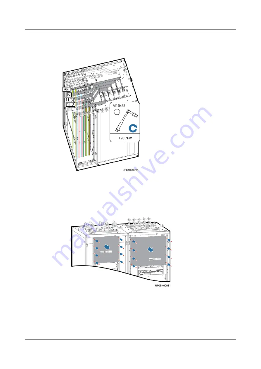
Step 7 Install mains input power cables.

Figure 6-69 Installing mains input power cables

Step 8 Install bypass input and output power cables.

Two power sources
Remove the copper bars between the mains and bypass input wiring

terminals.

Figure 6-70 Removing covers

Figure 6-71 Removing copper bars
a. Remove the screws that secure the guide rail of the SPD.
b. Place the SPD on the horizontal plate (without removing the cables).
c.

Remove the copper bars.

d. Reinstall the SPD.

UPS5000-H-(1200 kVA-1600 kVA)

User Manual (100 kVA Power Modules)

6 Installation

Issue 05 (2021-10-13)

Copyright © Huawei Technologies Co., Ltd.

127

Summary of Contents for UPS5000-H Series

Page 1: ...UPS5000 H 1200 kVA 1600 kVA User Manual 100 kVA Power Modules Issue 05 Date 2021 10 13 HUAWEI TECHNOLOGIES CO LTD ...

Page 2: ...cribed in this document may not be within the purchase scope or the usage scope Unless otherwise specified in the contract all statements information and recommendations in this document are provided AS IS without warranties guarantees or representations of any kind either express or implied The information in this document is subject to change without notice Every effort has been made in the prep...

Page 3: ...ion engineers Commissioning engineers Data configuration engineers Maintenance engineers Symbol Conventions The symbols that may be found in this document are defined as follows Symbol Description Indicates a hazard with a high level of risk which if not avoided will result in death or serious injury Indicates a hazard with a medium level of risk which if not avoided could result in death or serio...

Page 4: ...pment damage and environment deterioration Change History Changes between document issues are cumulative The latest document issue contains all updates made in previous issues Issue 05 2021 10 13 Added the three phase three wire model Issue 04 2021 08 03 Added the top air exhaust feature of the 1600 kVA model Added the S ECO mode Issue 03 2021 04 22 Added the 1600 kVA model Issue 02 2020 10 15 Upd...

Page 5: ... Mode 22 2 5 4 S ECO Mode 22 2 5 5 ECO Mode The System Can Work in ECO Mode If the Model or Hardware Does Not Support S ECO 24 2 5 6 Source Share Mode 24 3 Product Description 26 3 1 Model Description Three Phase Four Wire 26 3 2 Model Description Three Phase Three Wire 27 3 3 Cabinet Description 1200 kVA Three Phase Four Wire 28 3 3 1 Standard Configuration 28 3 3 2 Top Cabling Configuration 30 3...

Page 6: ...Cabling Configuration 46 3 6 4 Top Air Flow Configuration 47 3 6 5 Top Air Flow Top Cabling Configuration 48 4 Component Description 49 4 1 Power Module 49 4 2 Bypass Module 50 4 3 Control Module 52 4 3 1 Overview 52 4 3 2 ECM 52 4 3 3 Dry Contact Card 54 4 3 4 Monitoring Interface Card 57 4 4 Intelligent Detection Card 61 4 5 Surge Protection Box 64 4 6 MDU 64 5 Optional Components 67 5 1 List of...

Page 7: ...1 6 3 4 2 Installing Cables 138 6 3 5 Installation in Top Cabling Top Air Flow Configuration 138 6 3 5 1 Installing Cabinets 139 6 3 5 2 Installing Copper Bars and Cables 139 6 4 Single UPS Installation 1200 kVA Three Phase Three Wire 140 6 4 1 Installation in Standard Configuration 140 6 4 1 1 Installing Cabinets 140 6 4 1 2 Installing Rectifiers in the Inductor Cabinet 145 6 4 1 3 Installing Cab...

Page 8: ... 241 6 6 Single UPS Installation 1600 kVA Three Phase Three Wire 242 6 6 1 Installation in Standard Configuration 242 6 6 1 1 Installing Cabinets 243 6 6 1 2 Installing Rectifiers in the Inductor Cabinet 250 6 6 1 3 Installing Cables 251 6 6 2 Installation in Top Cabling Configuration 258 6 6 2 1 Installing Cabinets 258 6 6 2 2 Installing Rectifiers in the Inductor Cabinet 265 6 6 2 3 Installing C...

Page 9: ...rd 332 7 2 Shutting Down and Powering Off the UPS 333 7 3 Cold Starting the UPS Using Batteries 335 7 4 Transferring to Bypass Mode Manually 336 7 5 Setting the S ECO Mode 336 7 6 Setting ECO Mode 339 7 7 Testing Batteries 340 7 7 1 Lead Acid Battery Test 341 7 7 1 1 Performing a Forced Equalized Charging Test 341 7 7 1 2 Performing a Shallow Discharge Test 342 7 7 1 3 Performing a Capacity Test 3...

Page 10: ...ce 366 9 2 4 Annual Maintenance 367 10 Troubleshooting 369 11 Technical Specifications 372 11 1 Physical Specifications 372 11 2 Environmental Specifications 374 11 3 Safety Compliance and ECM Specifications 374 11 4 Mains Input Electrical Specifications 375 11 5 Bypass Input Electrical Specifications 376 11 6 Battery Electrical Specifications 376 11 7 Output Electrical Specifications 377 11 8 Sys...

Page 11: ...anty Follow local laws and regulations when installing operating or maintaining the equipment The safety instructions in this document are only supplements to local laws and regulations Huawei will not be liable for any consequences of the following circumstances Operation beyond the conditions specified in this document Installation or use in environments which are not specified in relevant inter...

Page 12: ...nstallation operation and maintenance Before handling a conductor surface or terminal measure the contact point voltage and ensure that there is no risk of electric shock After installing the equipment remove idle packing materials such as cartons foam plastics and cable ties from the equipment area In the case of a fire immediately leave the building or the equipment area and turn on the fire ala...

Page 13: ... caused during equipment transportation or installation in a timely manner Equipment with scratches cannot be exposed to an outdoor environment for a long period of time Before operations ensure that the equipment is firmly secured to the floor or other solid objects such as a wall or an installation rack Do not use water to clean electrical components inside or outside of a cabinet Do not change ...

Page 14: ...t Professionals personnel who are trained or experienced in equipment operations and are clear of the sources and degree of various potential hazards in equipment installation operation maintenance Trained personnel personnel who are technically trained have required experience are aware of possible hazards on themselves in certain operations and are able to take protective measures to minimize th...

Page 15: ...red facilities must be performed by qualified personnel Cabling When routing cables ensure that a distance of at least 30 mm exists between the cables and heat generating components or areas This prevents damage to the insulation layer of the cables Do not route cables behind the air intake and exhaust vents of the equipment Ensure that cables meet the VW 1 or ZB flame spread rating requirements o...

Page 16: ...ESD packaging materials before storing or transporting them Figure 1 1 Wearing an ESD wrist strap Neutral Ground Voltage It is recommended that the three phase loads be equalized and the neutral ground voltage be kept at less than 2 V to meet power distribution requirements 1 4 Installation Environment Requirements To prevent fire due to high temperature ensure that the ventilation vents or heat d...

Page 17: ... heights Wear personal protective equipment such as the safety helmet and safety belt or waist rope and fasten it to a solid structure Do not mount it on an insecure moveable object or metal object with sharp edges Make sure that the hooks will not slide off Set a restricted area and eye catching signs for working at heights to warn away irrelevant personnel Carry the operation machinery and tools...

Page 18: ...den or fiberglass ladders when you need to perform live working at heights When a step ladder is used ensure that the pull ropes are secured and the ladder is held firm Before using a ladder check that it is intact and confirm its load bearing capacity Do not overload it Ensure that the ladder is securely positioned The recommended angle for a ladder against the floor is 75 degrees as shown in the...

Page 19: ...or cables inside Metal shavings from drilling may short circuit boards inside the equipment Obtain consent from the customer and contractor before drilling holes Wear goggles and protective gloves when drilling holes When drilling holes protect the equipment from shavings After drilling clean up any shavings that have accumulated inside or outside the equipment Moving Heavy Objects DANGER When rem...

Page 20: ...icated personnel to take care of it Choose sea or a road with good conditions for transportation to ensure equipment safety Avoid tilt or jolt during transportation Move the cabinet with caution Any bumping or falling may damage the equipment Figure 1 2 Tilting angle of a cabinet 1 6 Device Running Safety The UPS is used for commercial and industrial purposes only It cannot be used as a power supp...

Page 21: ...s store them in a dry and clean environment If batteries are stored for more than 90 days charge them in time Otherwise the battery lifespan may be affected Install the UPS in an area far away from liquids Do not install it under areas prone to water leakage such as air conditioner vents ventilation vents or feeder windows of the equipment room Ensure that no liquid enters the UPS to prevent short...

Page 22: ...ts where the temperature and humidity are not controllable such as simple equipment rooms civil houses garages corridors and direct ventilation cabinets near the sea or houses with only roofs railway station platforms gymnasiums and aquariums Environments that are conducive for the growth of microorganisms such as fungus or mildew Environments where rodents such as mice and insects exist 1 7 Batte...

Page 23: ...tery Installation Before installing batteries observe the following safety precautions Install batteries in a well ventilated dry and cool environment that is far away from heat sources flammable materials moisture extensive infrared radiation organic solvents and corrosive gases Take fire prevention measures Place and secure batteries horizontally Note the polarities when installing batteries Do ...

Page 24: ...ws handle the leakage immediately Electrolyte overflow may damage the equipment It will corrode metal parts and boards and ultimately damage the boards If the electrolyte overflows follow the instructions of the battery manufacturer or neutralize the electrolyte by using sodium bicarbonate NaHCO3 or sodium carbonate Na2CO3 Lithium Battery The safety precautions for lithium batteries are similar to...

Page 25: ...ill be compromised Do not throw a lithium battery in fire When maintenance is complete return the waste lithium battery to the maintenance office 1 8 Others Exercise caution when manually shutting down the UPS inverter for transferring to bypass mode or when adjusting the UPS output voltage level or frequency Doing so may affect the power supply to equipment Exercise caution when setting battery p...

Page 26: ...res Simple Power bypass and control modules are hot swappable A common engineer can finish maintenance within 5 minutes Smooth capacity expansion is supported The initial investment on the UPS is reduced and the UPS operating efficiency is improved The UPS is configured with an SNMP card which reduces the management cost and features simple and flexible configurations Huawei NetEco easily implemen...

Page 27: ...apt to poor power grids The UPS has an output power factor PF of 1 0 which is suitable for linear and non linear loads with a PF greater than 0 5 This allows the UPS to connect to more loads and reduces customer investments The UPS passes reliability tests which focus on high temperature high humidity and dust adaptation The impact of environment on the UPS reliability is reduced 2 3 Application S...

Page 28: ...s can be connected in parallel For details about a parallel system where three phase three wire input and output cables are connected using a busway contact marketing engineers Dual bus system Supplies power to important loads in large and medium sized equipment rooms data centers and other places that require high reliability In addition to advantages of common parallel systems the dual bus syste...

Page 29: ...ovides redundant capacity even if only a single UPS is operating which ensures high reliability Figure 2 1 Typical application scenario of a single UPS Parallel System In a parallel system mains input bypass input and AC output terminals of UPSs are connected in parallel ECMs on different UPSs are connected over parallel cables to synchronize UPS outputs to supply power to loads If one UPS fails a...

Page 30: ...tion The UPS systems work in inverter mode or bypass mode Figure 2 3 Typical application scenario of a dual bus system consisting of single UPS systems 2 4 Working Principle The UPS is an online product It uses modular design which facilitates maintenance and capacity expansion The UPS uses the DSP technology for intelligent control The power module consists of a rectifier inverter and DC DC conve...

Page 31: ...as input harmonics glitches and voltage transients Figure 2 5 UPS conceptual diagram in normal mode 2 5 2 Bypass Mode When the UPS detects that the power module experiences overtemperature overload or other faults that may shut down the inverter the UPS automatically transfers to bypass mode At the same time the rectifier is started and charges batteries over a charger In bypass mode loads are pow...

Page 32: ...Mode If the mains input is abnormal or the rectifier becomes abnormal the UPS transfers to battery mode The power module obtains energy from batteries and the energy is converted into AC output by the inverter Figure 2 7 UPS conceptual diagram in battery mode 2 5 4 S ECO Mode UPS5000 H 1200 kVA 1600 kVA User Manual 100 kVA Power Modules 2 Product Overview Issue 05 2021 10 13 Copyright Huawei Techn...

Page 33: ...iciency It ensures uninterruptible 0 ms power supply and reduces the impact of load harmonics on the power grid This mode can be set on the LCD or WebUI When the bypass input voltage waveform is good the voltage and frequency are within the preset bypass range the PF is greater than 0 5 and the load rate is greater than 5 the UPS works in bypass mode preferentially and the inverter starts for hot ...

Page 34: ...de or inverter mode the rectifier is started all the time and charges batteries using a charger The ECO mode delivers a high efficiency Figure 2 9 UPS conceptual diagram in ECO mode NOTE Manual startup is required to ensure that the inverter is in standby state and the power flow has reached the inverter 2 5 6 Source Share Mode If the UPS works properly and the AC input power of rectifiers is insu...

Page 35: ...Figure 2 10 Conceptual diagram in source share mode UPS5000 H 1200 kVA 1600 kVA User Manual 100 kVA Power Modules 2 Product Overview Issue 05 2021 10 13 Copyright Huawei Technologies Co Ltd 25 ...

Page 36: ...ut capacity of 1200 kVA in full configuration supports a minimum of 200 kVA This document describes only the specifications of the 1200 kVA model 1600 kVA output capacity of 1600 kVA in full configuration supports a minimum of 200 kVA This document describes only the specifications of the 1600 kVA model 4 Switch configuration N no switch UPS5000 H 1200 kVA 1600 kVA User Manual 100 kVA Power Module...

Page 37: ...re Figure 3 2 Model number 1200K is used as an example Table 3 2 Model description No Item Description 1 Product category UPS5000 2 Product subcategory H high power density and high efficiency 3 Rated capacity 1200K output capacity of 1200 kVA in full configuration supports a minimum of 200 kVA This document describes only the specifications of the 1200 kVA model 1600 kVA output capacity of 1600 k...

Page 38: ...ured with a top cabling component cables can be routed in and out from the top If the system is configured with a bottom cabling cabinet cables can be routed in and out from the bottom 6 Configuration type N no neutral wire 3 3 Cabinet Description 1200 kVA Three Phase Four Wire 3 3 1 Standard Configuration Figure 3 3 UPS exterior UPS5000 H 1200 kVA 1600 kVA User Manual 100 kVA Power Modules 3 Prod...

Page 39: ...xes 4 Filler panel for an optional ECM extended subrack 5 Control module 6 Intelligent detection card 7 Bypass control module 8 Bypass modules UPS5000 H 1200 kVA 1600 kVA User Manual 100 kVA Power Modules 3 Product Description Issue 05 2021 10 13 Copyright Huawei Technologies Co Ltd 29 ...

Page 40: ...5 Appearance 1 Top cabling component optional including the top frame and transfer copper bar 2 UPS UPS5000 H 1200 kVA 1600 kVA User Manual 100 kVA Power Modules 3 Product Description Issue 05 2021 10 13 Copyright Huawei Technologies Co Ltd 30 ...

Page 41: ... 1 Bottom cabling cabinet optional including the top frame 2 Transfer copper bar for bottom cabling optional 3 UPS UPS5000 H 1200 kVA 1600 kVA User Manual 100 kVA Power Modules 3 Product Description Issue 05 2021 10 13 Copyright Huawei Technologies Co Ltd 31 ...

Page 42: ...w Configuration Figure 3 7 Appearance 1 Top air flow cabinet optional 2 UPS UPS5000 H 1200 kVA 1600 kVA User Manual 100 kVA Power Modules 3 Product Description Issue 05 2021 10 13 Copyright Huawei Technologies Co Ltd 32 ...

Page 43: ...tional 2 Top cabling component optional including the top frame and transfer copper bar 3 UPS 3 4 Cabinet Description 1200 kVA Three Phase Three Wire UPS5000 H 1200 kVA 1600 kVA User Manual 100 kVA Power Modules 3 Product Description Issue 05 2021 10 13 Copyright Huawei Technologies Co Ltd 33 ...

Page 44: ...Interior 1 SPDs and SPD switches 2 Power modules 3 Rectifiers 4 Surge protection boxes 5 Control module 6 Main switch QF of the inductor cabinet UPS5000 H 1200 kVA 1600 kVA User Manual 100 kVA Power Modules 3 Product Description Issue 05 2021 10 13 Copyright Huawei Technologies Co Ltd 34 ...

Page 45: ...trol module 12 Fans 3 4 2 Top Cabling Configuration Figure 3 11 Appearance 1 Top cabling component optional including the top frame and transfer copper bar 2 UPS 3 Inductor cabinet UPS5000 H 1200 kVA 1600 kVA User Manual 100 kVA Power Modules 3 Product Description Issue 05 2021 10 13 Copyright Huawei Technologies Co Ltd 35 ...

Page 46: ... cabling cabinet optional including the top frame 2 Transfer copper bar for bottom cabling optional 3 UPS 4 Inductor cabinet UPS5000 H 1200 kVA 1600 kVA User Manual 100 kVA Power Modules 3 Product Description Issue 05 2021 10 13 Copyright Huawei Technologies Co Ltd 36 ...

Page 47: ...ation Figure 3 13 Appearance 1 Top air flow cabinet optional 2 UPS 3 Inductor cabinet UPS5000 H 1200 kVA 1600 kVA User Manual 100 kVA Power Modules 3 Product Description Issue 05 2021 10 13 Copyright Huawei Technologies Co Ltd 37 ...

Page 48: ... Top cabling component optional including the top frame and transfer copper bar 3 UPS 4 Inductor cabinet 3 5 Cabinet Description 1600 kVA Three Phase Four Wire UPS5000 H 1200 kVA 1600 kVA User Manual 100 kVA Power Modules 3 Product Description Issue 05 2021 10 13 Copyright Huawei Technologies Co Ltd 38 ...

Page 49: ... cabinet 2 3 Bypass cabinet Figure 3 16 UPS structure with the door open 1 SPDs and SPD switches 2 Power modules 3 Surge protection boxes UPS5000 H 1200 kVA 1600 kVA User Manual 100 kVA Power Modules 3 Product Description Issue 05 2021 10 13 Copyright Huawei Technologies Co Ltd 39 ...

Page 50: ... control module 9 Bypass modules 3 5 2 Top Cabling Configuration Figure 3 17 UPS top cabling component 1 Top cabling component optional including the top frame and transfer copper bar 2 UPS UPS5000 H 1200 kVA 1600 kVA User Manual 100 kVA Power Modules 3 Product Description Issue 05 2021 10 13 Copyright Huawei Technologies Co Ltd 40 ...

Page 51: ...ng cabinet optional including the top frame 2 Power cabinet 1 3 Transfer copper bar for bottom cabling optional 4 Power cabinet 2 5 Bypass cabinet UPS5000 H 1200 kVA 1600 kVA User Manual 100 kVA Power Modules 3 Product Description Issue 05 2021 10 13 Copyright Huawei Technologies Co Ltd 41 ...

Page 52: ...t 2 4 Bypass cabinet 3 5 5 Top Air Flow Top Cabling Configuration Figure 3 20 UPS top cabling component top air flow cabinet 1 Top air flow cabinet optional 2 Power cabinet 1 3 Power cabinet 2 UPS5000 H 1200 kVA 1600 kVA User Manual 100 kVA Power Modules 3 Product Description Issue 05 2021 10 13 Copyright Huawei Technologies Co Ltd 42 ...

Page 53: ... Description 1600 kVA Three Phase Three Wire 3 6 1 Standard Configuration Figure 3 21 Appearance 1 Power cabinet 1 2 Power cabinet 2 3 Bypass cabinet 4 Inductor cabinet UPS5000 H 1200 kVA 1600 kVA User Manual 100 kVA Power Modules 3 Product Description Issue 05 2021 10 13 Copyright Huawei Technologies Co Ltd 43 ...

Page 54: ...ch QF of the inductor cabinet 6 Control module 7 Intelligent detection board 8 Bypass fan PSU 9 Inductor cabinet fan power switches QS1 4 10 Bypass modules 11 Bypass control module 12 Fans UPS5000 H 1200 kVA 1600 kVA User Manual 100 kVA Power Modules 3 Product Description Issue 05 2021 10 13 Copyright Huawei Technologies Co Ltd 44 ...

Page 55: ...Power cabinet 2 3 Top cabling component optional including the top frame and transfer copper bar 4 Bypass cabinet 5 Inductor cabinet UPS5000 H 1200 kVA 1600 kVA User Manual 100 kVA Power Modules 3 Product Description Issue 05 2021 10 13 Copyright Huawei Technologies Co Ltd 45 ...

Page 56: ...l including the top frame 2 Power cabinet 1 3 Transfer copper bar for bottom cabling optional 4 Power cabinet 2 5 Bypass cabinet 6 Inductor cabinet UPS5000 H 1200 kVA 1600 kVA User Manual 100 kVA Power Modules 3 Product Description Issue 05 2021 10 13 Copyright Huawei Technologies Co Ltd 46 ...

Page 57: ...ance 1 Top air flow cabinet optional 2 Power cabinet 1 3 Power cabinet 2 4 Bypass cabinet 5 Inductor cabinet UPS5000 H 1200 kVA 1600 kVA User Manual 100 kVA Power Modules 3 Product Description Issue 05 2021 10 13 Copyright Huawei Technologies Co Ltd 47 ...

Page 58: ...al 2 Power cabinet 1 3 Power cabinet 2 4 Bypass cabinet 5 Top cabling component optional including the top frame and transfer copper bar 6 Inductor cabinet UPS5000 H 1200 kVA 1600 kVA User Manual 100 kVA Power Modules 3 Product Description Issue 05 2021 10 13 Copyright Huawei Technologies Co Ltd 48 ...

Page 59: ...Alarm indicator 5 Fault indicator 6 Ready switch 7 Output ports 8 Input ports Table 4 1 Indicator description Indicator Colo r Status Description Running indicator Gree n Stead y on The system is working in inverter mode Blinki ng at long interv als The inverter is ready and in standby state blinking at 0 5 Hz on for 1s and off for 1s The inverter is not started blinking at 0 2 Hz on for 2 5s and ...

Page 60: ...r or rectifier Off There is no critical alarm for the inverter or rectifier or the software is being upgraded Table 4 2 Specifications Item Specifications Rated output capacity 100 kVA 100 kW Dimensions H x W x D 130 mm x 442 mm x 750 mm Weight 55 kg 4 2 Bypass Module The UPS works in bypass mode under the following circumstances The S ECO or ECO mode is used and the bypass voltage is within the s...

Page 61: ...s Blinking fast The bypass is not configured or the software is being upgraded blinking at 4 Hz on for 0 125s and off for 0 125s Off The bypass software is being upgraded Alarm indicator Yellow Steady on A minor alarm is generated for the bypass Off There is no minor alarm for the bypass or the software is being upgraded Fault indicator Red Steady on A critical alarm is generated for the bypass Of...

Page 62: ...of the control module 1 Ground terminal 2 Parallel port 1 3 BSC port 1 4 Ready switch on ECM 1 5 ECM 1 indicators 6 Parallel port 2 7 BSC port 2 8 Ready switch on ECM 2 9 ECM 2 indicators 10 Dry contact card 11 Dry contacts 12 Monitoring display unit MDU port 13 RS485 port 14 FE port 15 COM2 port 16 COM1 port 17 Battery temperature sensor port 18 Optional card subrack cover NOTE Ports are protecte...

Page 63: ... Figure 4 4 Appearance Table 4 5 Port description Silk Screen Description PARALLEL The PARALLEL port transmits parallel signals between racks BSC The BSC port is used in a dual bus system to synchronize output frequencies and phases between UPS systems ensuring that two buses can switch with each other BSC cables are hot swappable NOTE No parallel cable is required for a single UPS Table 4 6 Indic...

Page 64: ... Off The ECM has no critical alarm or the software of the ECM is being upgraded Figure 4 5 CAN communication logic 4 3 3 Dry Contact Card The dry contact card allows the UPS to detect and manage the switch status of the battery system including the external battery switch and implement remote emergency power off EPO The dry contact card is 0 5 U high and hot swappable UPS5000 H 1200 kVA 1600 kVA U...

Page 65: ... 30 V AC and 1 0 A During cable connection ensure that the voltage and current do not exceed these maximum values Figure 4 6 Appearance Table 4 7 Functions of control signal ports on the dry contact card Silk Screen Signal Description Status Description Initial Status BTG Port for monitoring battery grounding failures Closed There is a battery grounding failure Open There is no battery grounding f...

Page 66: ...ring the UPS output circuit breaker Closed The UPS output circuit breaker is ON Open The UPS output circuit breaker is OFF Closeda SWITCH STATUS_0V Port for signal ground SWITCH STATUS_MT Port for monitoring the maintenance switch Open The maintenance switch is ON Closed The maintenance switch is OFF Opena SWITCH STATUS_0V Port for signal ground SWITCH STATUS_BP Port for monitoring the bypass inpu...

Page 67: ...ork management port The MDU monitors the UPS allows users to set parameters delivers commands reports system information and displays key UPS information and parameters on the LCD NOTICE The FE port resembles the RS485 port Therefore follow the silk screens when you connect communications cables If you mistake the RS485 port as the FE port during cable connection the WebUI communication fails If y...

Page 68: ...d Battery EOD Configure power segment settings based on backup time COM DO_2 NO COM DO_3 NO COM DO_4 NO COM DB26 MDU Supports FE RS485 I2C CAN and other signals Battery temperature sensor port B_TEMP Connects to an indoor battery temperature sensor Southbound communicati ons port 1 COM1 Supported protocol Modbus RTU Connects to an ambient temperature and humidity sensor over two wires Southbound c...

Page 69: ...485 cables and FE cables must be shielded cables Figure 4 8 and Figure 4 9 are recommended wiring methods for DO ports Figure 4 8 Wiring method 1 Figure 4 9 Wiring method 2 Figure 4 10 COM1 port pins UPS5000 H 1200 kVA 1600 kVA User Manual 100 kVA Power Modules 4 Component Description Issue 05 2021 10 13 Copyright Huawei Technologies Co Ltd 59 ...

Page 70: ...PORT Figure 4 11 COM2 port pins Table 4 10 Pin definitions for the COM2 port Pin Description 1 RS485 2 RS485 3 4 RS485 5 RS485 6 GND 7 CANH0 8 CANL0 UPS5000 H 1200 kVA 1600 kVA User Manual 100 kVA Power Modules 4 Component Description Issue 05 2021 10 13 Copyright Huawei Technologies Co Ltd 60 ...

Page 71: ...Twist cables to pin 2 and pin 5 into one and then connect it to RS485 4 4 Intelligent Detection Card In the integrated UPS solution the intelligent detection card detects the temperatures of the copper bars switches and environments of the battery bypass input mains input output bypass input of the switch cabinet mains input of the switch cabinet and output of the switch cabinet and monitors the s...

Page 72: ...ff Indicates that the intelligent detection card is powered off RUN Green Blinking at 0 5 Hz The intelligent detection board is running properly Blinking at 4 Hz The communication is interrupted ALM Red Steady on An alarm is generated Off No alarm is generated NOTE Signal cables must be double insulated twisted cables If the cable length is within 25 50 m the cross sectional area must be 0 5 1 5 m...

Page 73: ...for the COM_OUT port Pin Description 1 RS485 2 RS485 3 4 RS485 5 RS485 6 7 CANH 8 CANL Figure 4 15 FE_1 port pins UPS5000 H 1200 kVA 1600 kVA User Manual 100 kVA Power Modules 4 Component Description Issue 05 2021 10 13 Copyright Huawei Technologies Co Ltd 63 ...

Page 74: ...e phase PE power system Figure 4 16 Surge protection box 1 Working status indicators 4 6 MDU The MDU allows you to control UPS operations view the running status and alarms and set parameters For details see the UPS5000 Monitoring Module User Manual Dimensions H x W x D 175 mm x 264 mm x 40 mm UPS5000 H 1200 kVA 1600 kVA User Manual 100 kVA Power Modules 4 Component Description Issue 05 2021 10 13...

Page 75: ...been generated and the buzzer buzzes intermittently at 2 Hz Green The UPS is running properly or a warning has been generated Off The MDU is powered off NOTE The indicator on the MDU panel is yellow when the bypass supplies power in non ECO mode Figure 4 18 MDU ports UPS5000 H 1200 kVA 1600 kVA User Manual 100 kVA Power Modules 4 Component Description Issue 05 2021 10 13 Copyright Huawei Technolog...

Page 76: ...ing inspection NOTE Only Huawei service engineers or authorized service engineers are allowed to use the WiFi module To ensure security remove the WiFi module immediately after use Insert a USB flash drive to import and export configuration files export run logs and upgrade software 8 SD Reserved 9 DIP switch Implements specific functions by using the DIP switch and specific buttons controls the C...

Page 77: ...ins and bypass backfeed and provides protection ECM extended subrack Installed when the UPS is equipped with a backfeed protection card and dry contact extended card Ambient temperature and humidity T H sensor Monitors ambient temperature and humidity BSC cable 5 m 10 m 15 m 60 m Transmits bus synchronization signals in a dual bus system Parallel cable 5 m 10 m 15 m Connects UPSs in parallel Top a...

Page 78: ...e groups of electric relay output ports for dry contact signals and five groups of signal input ports to implement various alarm and control functions as required A maximum of one dry contact extended card supported in the power monitoring subrack The card is hot swappable Figure 5 1 Appearance NOTICE For dry contact outputs the rated DC voltage and current are 24 V DC and 0 6 A and the maximum va...

Page 79: ...supplied Mains supplies power ECO mode Battery test Batt volt below thres Rack output overload Battery temp abnormal and Battery EOD MUS07A DO_1 is set to Low batt volt by default Others are reserved by default DOs transmit passive dry contact output signals Users need to connect external power supply to DOs COM DO_2 NO COM DO_3 NO COM DO_4 NO COM DO_5 NO COM Inpu t DI_1 All DIs are reserved On th...

Page 80: ...ction card sends signals to trigger alarm signals or quickly disconnect the feedback loop The card is hot swappable Figure 5 4 Appearance Figure 5 5 Ports on the backfeed protection card UPS5000 H 1200 kVA 1600 kVA User Manual 100 kVA Power Modules 5 Optional Components Issue 05 2021 10 13 Copyright Huawei Technologies Co Ltd 70 ...

Page 81: ...ection BFP_NO The BFP port is the signal port for the bypass backfeed protection NO and COM are normally open contacts NC and COM are normally closed contacts When a backfeed occurs the normally open contacts are closed and the normally closed contacts are open BFP_COM BFP_NC RSV reserved RSV_NO Reserved RSV_COM RSV_NC 5 4 BCB Box The BCB box controls the connection between battery strings and the...

Page 82: ... rating 20 20 20 5 5 Ambient T H Sensor The ambient temperature and humidity T H sensor monitors the ambient temperature and humidity in the equipment room to ensure that the equipment works properly The ambient T H sensor can also be used as a battery temperature sensor The monitoring module distinguishes these two types of sensors through their DIP switch settings UPS5000 H 1200 kVA 1600 kVA Use...

Page 83: ... RJ11 port on each T H sensor Figure 5 8 RJ11 port Table 5 4 Pins on the RJ11 port Pin No Signal 1 GND 2 3 S_RS485B_R 4 S_RS485B_R 5 6 12V_OUT 5 6 Top Air Flow Cabinet Applies to the top airflow scenario UPS5000 H 1200 kVA 1600 kVA User Manual 100 kVA Power Modules 5 Optional Components Issue 05 2021 10 13 Copyright Huawei Technologies Co Ltd 73 ...

Page 84: ...abinet Applies to the bottom cabling scenario Cabinet dimensions H x W x D 2000 mm x 400 mm x 1000 mm excluding the top frame and copper bars For details about the appearance of the combination with the UPS see the section about cabinet description UPS5000 H 1200 kVA 1600 kVA User Manual 100 kVA Power Modules 5 Optional Components Issue 05 2021 10 13 Copyright Huawei Technologies Co Ltd 74 ...

Page 85: ...s copper bars at the rear of the cabinet Figure 5 11 Appearance 5 9 Top Cabling Component Applies to the top cabling scenario UPS5000 H 1200 kVA 1600 kVA User Manual 100 kVA Power Modules 5 Optional Components Issue 05 2021 10 13 Copyright Huawei Technologies Co Ltd 75 ...

Page 86: ...gure 5 13 Top frame 1200 kVA Figure 5 14 Copper bar assembly 1600 kVA Figure 5 15 Top frame 1600 kVA UPS5000 H 1200 kVA 1600 kVA User Manual 100 kVA Power Modules 5 Optional Components Issue 05 2021 10 13 Copyright Huawei Technologies Co Ltd 76 ...

Page 87: ... Rectifiers 2 Main switch QF of the inductor cabinet 3 Inductor cabinet fan power switches QS1 4 4 Fans 5 10 1 Rectifier A rectifier converts AC input power into stable DC power for the fan in the inductor cabinet UPS5000 H 1200 kVA 1600 kVA User Manual 100 kVA Power Modules 5 Optional Components Issue 05 2021 10 13 Copyright Huawei Technologies Co Ltd 77 ...

Page 88: ...The rectifier is loading an application program Alarm indicator Yellow Off The rectifier has no protection alarm Steady on The rectifier has generated a warning due to ambient overtemperature The rectifier has generated a shutdown alarm for protection due to ambient overtemperature or undertemperature AC input overvoltage or undervoltage protection has been triggered The rectifier is hibernating U...

Page 89: ...that the alarm indicator blinks at 0 5 Hz Fault indicator Red Off The rectifier is normal Steady on The rectifier locks out due to output overvoltage The rectifier has no output due to an internal fault Table 5 7 Specifications Item Specifications Dimensions H x W x D 40 8 mm x 95 5 mm x 208 mm Weight 1 5 kg UPS5000 H 1200 kVA 1600 kVA User Manual 100 kVA Power Modules 5 Optional Components Issue ...

Page 90: ... block and shunt release If a third party power supply is used the voltage is less than or equal to 240 V AC and the current is less than 6 A prepare a 6 A fuse shunt release and cable 0 5 1 3 mm2 cable recommended the actual cable size must meet the requirements of the backfeed protection card fuse terminal block and shunt release In a parallel system the length and specifications of power cables...

Page 91: ...ir flow cabinet do not install devices that are easy to swing on the top of the UPS Otherwise the devices may fall off 6 1 1 2 Installation Clearances Three Phase Four Wire Reserve the following clearances around the cabinet to facilitate operations and ventilation Reserve a clearance of at least 950 mm from the front of the cabinet for ventilation and operations Reserve a clearance of at least 50...

Page 92: ...tandard configuration 1200 kVA Figure 6 2 Space planning for top cabling configuration 1200 kVA UPS5000 H 1200 kVA 1600 kVA User Manual 100 kVA Power Modules 6 Installation Issue 05 2021 10 13 Copyright Huawei Technologies Co Ltd 82 ...

Page 93: ...om cabling configuration 1200 kVA Figure 6 4 Space planning for top air flow configuration 1200 kVA UPS5000 H 1200 kVA 1600 kVA User Manual 100 kVA Power Modules 6 Installation Issue 05 2021 10 13 Copyright Huawei Technologies Co Ltd 83 ...

Page 94: ...ling top air flow configuration 1200 kVA Figure 6 6 Space planning for standard configuration 1600 kVA UPS5000 H 1200 kVA 1600 kVA User Manual 100 kVA Power Modules 6 Installation Issue 05 2021 10 13 Copyright Huawei Technologies Co Ltd 84 ...

Page 95: ...cabling configuration 1600 kVA Figure 6 8 Space planning for bottom cabling configuration 1600 kVA UPS5000 H 1200 kVA 1600 kVA User Manual 100 kVA Power Modules 6 Installation Issue 05 2021 10 13 Copyright Huawei Technologies Co Ltd 85 ...

Page 96: ...igure 6 10 Space planning for top cabling top air flow configuration 1600 kVA 6 1 1 3 Installation Clearances Three Phase Three Wire UPS5000 H 1200 kVA 1600 kVA User Manual 100 kVA Power Modules 6 Installation Issue 05 2021 10 13 Copyright Huawei Technologies Co Ltd 86 ...

Page 97: ...ions Reserve a clearance of at least 500 mm from the rear of the cabinet for ventilation Reserve a clearance of at least 800 mm if you need to perform operations at the rear of the cabinet If the top air flow cabinet is configured no space needs to be reserved at the rear Figure 6 11 Space planning for standard configuration 1200 kVA UPS5000 H 1200 kVA 1600 kVA User Manual 100 kVA Power Modules 6 ...

Page 98: ...cabling configuration 1200 kVA Figure 6 13 Space planning for bottom cabling configuration 1200 kVA UPS5000 H 1200 kVA 1600 kVA User Manual 100 kVA Power Modules 6 Installation Issue 05 2021 10 13 Copyright Huawei Technologies Co Ltd 88 ...

Page 99: ...low configuration 1200 kVA Figure 6 15 Space planning for top cabling top air flow configuration 1200 kVA UPS5000 H 1200 kVA 1600 kVA User Manual 100 kVA Power Modules 6 Installation Issue 05 2021 10 13 Copyright Huawei Technologies Co Ltd 89 ...

Page 100: ...tandard configuration 1600 kVA Figure 6 17 Space planning for top cabling configuration 1600 kVA UPS5000 H 1200 kVA 1600 kVA User Manual 100 kVA Power Modules 6 Installation Issue 05 2021 10 13 Copyright Huawei Technologies Co Ltd 90 ...

Page 101: ...om cabling configuration 1600 kVA Figure 6 19 Space planning for top air flow configuration 1600 kVA UPS5000 H 1200 kVA 1600 kVA User Manual 100 kVA Power Modules 6 Installation Issue 05 2021 10 13 Copyright Huawei Technologies Co Ltd 91 ...

Page 102: ...ls and instruments required for the installation Table 6 1 Tools and instruments Tools and Instruments Electric pallet truck Manual pallet truck Step ladder Rubber mallet Hammer drill with a Φ16 drill bit Hand held electric drill Hole saw Heat gun UPS5000 H 1200 kVA 1600 kVA User Manual 100 kVA Power Modules 6 Installation Issue 05 2021 10 13 Copyright Huawei Technologies Co Ltd 92 ...

Page 103: ...oves Protective gloves Insulation gloves Insulated protective shoes Torque screwdriver Cable cutter Brush Flat head screwdriver 2 5 mm Phillips screwdriver M3 M4 M5 M6 M8 Insulated torque wrench M6 M8 M12 M16 Heat shrink tubing Insulated adjustable wrench UPS5000 H 1200 kVA 1600 kVA User Manual 100 kVA Power Modules 6 Installation Issue 05 2021 10 13 Copyright Huawei Technologies Co Ltd 93 ...

Page 104: ...evice RCD is not recommended If the top cabling component and bottom cabling cabinet are not configured copper bars need to be prepared for the mains input bypass input and output which cannot be directly connected using cables If the top cabling component and bottom cabling cabinet are not configured prepare wiring copper bars for mains input bypass input and output based on the following drawing...

Page 105: ...ense busway Figure 6 22 Top view of the distance between copper bars on the top of power cabinet 2 and the bypass cabinet 1600 kVA unit mm 1 Recommended space for connector boxes If the mains input and bypass input share a power source a connector box must be deployed for the copper bars that are not installed in the busway Copper bars must not be exposed 2 Space for the dense busway UPS5000 H 120...

Page 106: ...bars on the top 1200 kVA unit mm Figure 6 24 Front view of the distance between copper bars on the top 1600 kVA unit mm UPS5000 H 1200 kVA 1600 kVA User Manual 100 kVA Power Modules 6 Installation Issue 05 2021 10 13 Copyright Huawei Technologies Co Ltd 96 ...

Page 107: ...m Figure 6 26 Input and output copper bar specifications 1600 kVA unit mm Figure 6 27 Battery copper bar wiring holes 1200 kVA unit mm UPS5000 H 1200 kVA 1600 kVA User Manual 100 kVA Power Modules 6 Installation Issue 05 2021 10 13 Copyright Huawei Technologies Co Ltd 97 ...

Page 108: ...llel system the length and specifications of power cables on each UPS should be the same to achieve current equalization in bypass mode The power cables include bypass input power cables and UPS output power cables The cables need to be selected according to the site survey data The cable recommendation is for your reference only Table 6 2 Recommended power cable cross sectional areas 900 1200 kVA...

Page 109: ...0 2 x 240 2 x 240 Battery input lead acid battery Nominal battery discharge current A 1995 2216 2438 2660 Maximum battery discharge current A 2389 2654 2920 3185 Recomme nded cross sectional area mm2 6 x 240 6 x 240 6 x 240 6 x 240 6 x 240 6 x 240 6 x 240 6 x 240 PE 2 x 240 2 x 240 2 x 240 2 x 240 Battery input SmartLi Nominal battery discharge current A 1870 2078 2286 2493 Maximum battery dischar...

Page 110: ...40 8 x 240 8 x 240 N 7 x 240 7 x 240 8 x 240 8 x 240 PE 2 x 240 2 x 240 2 x 240 2 x 240 Output Output current A 1975 2127 2279 2431 Recomme nded cross sectional area mm2 U 7 x 240 7 x 240 8 x 240 8 x 240 V 7 x 240 7 x 240 8 x 240 8 x 240 W 7 x 240 7 x 240 8 x 240 8 x 240 N 7 x 240 7 x 240 8 x 240 8 x 240 PE 2 x 240 2 x 240 2 x 240 2 x 240 Battery input lead acid battery Nominal battery discharge c...

Page 111: ...t of forty 12 V batteries at 480 V in standard configuration The maximum battery discharge current refers to the current when forty 12 V batteries in standard configuration that is two hundred and forty 2 V battery cells 1 67 V cell stop discharging The battery cable specifications are selected based on 40 batteries by default and compatible with application scenarios with 30 50 batteries When the...

Page 112: ...inals M6 20 mm 4 5 N m Table 6 5 Recommended input output circuit breakers Circuit Breaker Name Specific ationsa 900 kVA Specific ationsa 1000 kVA Specific ationsa 1100 kVA Specific ationsa 1200 kVA Specific ationsa 1300 kVA Specific ationsa 1400 kVA Specific ationsa 1500 kVA Specific ationsa 1600 kVA Mains input circuit breaker 2000 A 3P 2000 A 3P 2500 A 3P 2500 A 3P 3000 A 3P 3000 A 3P 3200 A 3P...

Page 113: ...pling which may damage the UPS After placing the case in the installation position unpack it with caution to prevent scratches Keep the UPS steady during unpacking If the UPS installation environment is in poor condition and the UPS needs to be stored for a long time after it is unpacked take measures to prevent dust It is recommended that the UPS be wrapped with the original plastic coat Procedur...

Page 114: ...side and around cabinets Prepare terminals onsite The length of the copper wire should be the same as that of the part of the terminal that covers the conductor Procedure Step 1 Route a cable into the cabinet and bind it to a nearby beam Step 2 Pull the cable to the copper bar to which the cable is to be connected determine the cable length and mark the cable at the position where the cable is to ...

Page 115: ... the door support at the bottom of the cabinet to prevent paint flake off and deformation Otherwise the front door will not be properly closed Do not step on the top of the cabinet to prevent deformation or collapse 6 3 1 Installation in Standard Configuration 6 3 1 1 Installing Cabinets Installation on the Floor NOTICE Ensure that the installation floor is flat Step 1 Determine the cabinet instal...

Page 116: ...nd vertically insert it into the hole Knock the expansion bolt using a rubber mallet until the expansion sleeve is fully inserted into the hole 3 Partially tighten the expansion bolt 4 Remove the bolt spring washer and flat washer NOTICE Knock the expansion bolt into the hole until the expansion sleeve completely fits into the hole The expansion sleeve must be completely buried under the ground to...

Page 117: ...abinets to the installation positions Step 4 Secure the cabinets Figure 6 34 Securing the cabinets NOTE To meet the requirements of 9 intensity earthquake resistance tighten 16 screws at the bottom Step 5 Install anchor baffle plates UPS5000 H 1200 kVA 1600 kVA User Manual 100 kVA Power Modules 6 Installation Issue 05 2021 10 13 Copyright Huawei Technologies Co Ltd 107 ...

Page 118: ...unting holes for the cabinets based on the marking off template for installation on channel steel Drill mounting holes on the channel steel using a hammer drill If the nuts cannot be placed on the side of the channel steel drill holes near the mounting holes on the side of the channel steel to place the nuts for securing the cabinet You are advised to use an electric pallet truck to move the cabin...

Page 119: ...l The channel steel model installation mode whether holes need to be drilled on its sides hole size and the actual number of cabinets are determined based on site survey data Figure 6 37 Recommended channel steel dimensions unit mm 6 3 1 2 Installing Cables Context Figure 6 38 Copper bar positions 1 Battery input 2 Mains input 3 Battery PE 4 UPS output 5 Bypass input UPS5000 H 1200 kVA 1600 kVA Us...

Page 120: ...mains input and bypass input NOTICE Perform this step only when the mains input and bypass input use different power sources 1 Remove the covers Figure 6 40 Removing the covers 2 Remove the screws that secure the guide rail of the SPD 3 Place the SPD on the horizontal plate without removing the cables 4 Remove the copper bars UPS5000 H 1200 kVA 1600 kVA User Manual 100 kVA Power Modules 6 Installa...

Page 121: ...rk together Figure 6 41 Removing copper bars Step 3 Install battery cables NOTE The figure uses the cable connection between the UPS and the SmartLi as an example Battery cables are connected to each SmartLi UPS5000 H 1200 kVA 1600 kVA User Manual 100 kVA Power Modules 6 Installation Issue 05 2021 10 13 Copyright Huawei Technologies Co Ltd 111 ...

Page 122: ...he ground bar in the equipment room based on the site survey Step 4 Install top supports and covers of the battery terminal protective covers Figure 6 43 Installing top supports and covers Step 5 Install input and output busbars UPS5000 H 1200 kVA 1600 kVA User Manual 100 kVA Power Modules 6 Installation Issue 05 2021 10 13 Copyright Huawei Technologies Co Ltd 112 ...

Page 123: ...t on the monitoring interface card Connection required only for SmartLi 2 0 If the UPS needs to connect to the SmartLi connect the COM port on the monitoring interface unit in the master SmartLi cabinet to the COM2 port on the monitoring interface card NOTE Do not bind signal cables and power cables together RS485 cables and FE cables must be shielded cables The figure uses the cable connection be...

Page 124: ...ars and Cables Context Figure 6 45 Copper bar positions 1 Battery input 2 Mains input 3 Battery PE 4 UPS output 5 Bypass input NOTE The number and colors of cables in the following figures are for reference only Procedure Step 1 Install conversion copper bars from right to left and remove the left and right connecting kits from the top of the cabinets Figure 6 46 Installing conversion copper bars ...

Page 125: ...gure 6 49 Removing copper bars a Remove the screws that secure the guide rail of the SPD b Place the SPD on the horizontal plate without removing the cables c Remove the copper bars d Reinstall the SPD NOTICE The mains and bypass copper bars are heavy To prevent personal injury or device damage arrange for two persons to work together UPS5000 H 1200 kVA 1600 kVA User Manual 100 kVA Power Modules 6...

Page 126: ...inals or connect the bypass input power cable Step 4 Install battery cables NOTE The number and colors of cables are for reference only The figure uses the cable connection between the UPS and the SmartLi as an example Connect battery cables to each SmartLi UPS5000 H 1200 kVA 1600 kVA User Manual 100 kVA Power Modules 6 Installation Issue 05 2021 10 13 Copyright Huawei Technologies Co Ltd 116 ...

Page 127: ...box to the battery PE of the UPS or the ground bar in the equipment room based on the site survey Step 5 Install top frames No 14 17 Figure 6 52 Installing top frames Step 6 Install top covers UPS5000 H 1200 kVA 1600 kVA User Manual 100 kVA Power Modules 6 Installation Issue 05 2021 10 13 Copyright Huawei Technologies Co Ltd 117 ...

Page 128: ... on the monitoring interface card If the UPS needs to connect to an external network management device connect the external network management device to the RS485 port on the monitoring interface card Connection required only for SmartLi 2 0 If the UPS needs to connect to the SmartLi connect the COM port on the monitoring interface unit in the master SmartLi cabinet to the COM2 port on the monitor...

Page 129: ...i cabinet End 6 3 3 Installation in Bottom Cabling Configuration Cables can be routed from the bottom if the optional bottom cabling cabinet is configured 6 3 3 1 Installing Cabinets Installation on the Floor NOTICE Ensure that the installation floor is flat Step 1 Determine the cabinet installation positions on the floor based on the holes in the marking off template for floor installation UPS500...

Page 130: ...the expansion bolt and vertically insert it into the hole Knock the expansion bolt using a rubber mallet until the expansion sleeve is fully inserted into the hole 3 Partially tighten the expansion bolt 4 Remove the bolt spring washer and flat washer NOTICE Knock the expansion bolt into the hole until the expansion sleeve completely fits into the hole The expansion sleeve must be completely buried...

Page 131: ... cabinet Step 5 Move the cabinets to the installation positions Step 6 Combine the bottom cabling cabinet with other cabinets in the sequence of bottom top and middle and remove the connecting kits on the top of the left and right sides Figure 6 58 Combining the bottom cabling cabinet Step 7 Secure the cabinets UPS5000 H 1200 kVA 1600 kVA User Manual 100 kVA Power Modules 6 Installation Issue 05 2...

Page 132: ...nels on both sides of the bottom cabling cabinet Step 9 Install anchor baffle plates Figure 6 60 Installing anchor baffle plates End UPS5000 H 1200 kVA 1600 kVA User Manual 100 kVA Power Modules 6 Installation Issue 05 2021 10 13 Copyright Huawei Technologies Co Ltd 122 ...

Page 133: ...o place the nuts for securing the cabinet You are advised to use an electric pallet truck to move the cabinet to the mounting holes in the channel steel Use M12x60 bolts to secure the cabinets on the channel steel Figure 6 61 Hole positions on the channel steel optional 1 Hole positions on the channel steel The figure uses the C shaped channel steel with the opening facing downwards and one cabine...

Page 134: ...cables in the following figures are for reference only Procedure Step 1 Remove the top covers from the bottom cabling cabinet and the battery copper bars Figure 6 64 Removing the covers and battery copper bars Step 2 Install epoxy boards No 1 to 8 UPS5000 H 1200 kVA 1600 kVA User Manual 100 kVA Power Modules 6 Installation Issue 05 2021 10 13 Copyright Huawei Technologies Co Ltd 124 ...

Page 135: ...o 32 and 40 from right to left Figure 6 66 Installing copper bars Step 4 Install bypass input copper bars No 20 to 23 and output copper bars No 24 to 27 from right to left UPS5000 H 1200 kVA 1600 kVA User Manual 100 kVA Power Modules 6 Installation Issue 05 2021 10 13 Copyright Huawei Technologies Co Ltd 125 ...

Page 136: ...he bottom cabling cabinet Step 6 Install equipotential ground cable for cabinets Figure 6 68 Installing equipotential ground cable for cabinets UPS5000 H 1200 kVA 1600 kVA User Manual 100 kVA Power Modules 6 Installation Issue 05 2021 10 13 Copyright Huawei Technologies Co Ltd 126 ...

Page 137: ...nd bypass input wiring terminals Figure 6 70 Removing covers Figure 6 71 Removing copper bars a Remove the screws that secure the guide rail of the SPD b Place the SPD on the horizontal plate without removing the cables c Remove the copper bars d Reinstall the SPD UPS5000 H 1200 kVA 1600 kVA User Manual 100 kVA Power Modules 6 Installation Issue 05 2021 10 13 Copyright Huawei Technologies Co Ltd 1...

Page 138: ...t power cables One power source If the mains input and bypass input share a power source you do not need to remove the copper bar between the mains and bypass input terminals or connect the bypass input power cable Step 9 Install battery cables UPS5000 H 1200 kVA 1600 kVA User Manual 100 kVA Power Modules 6 Installation Issue 05 2021 10 13 Copyright Huawei Technologies Co Ltd 128 ...

Page 139: ...ng interface card Connection required only for SmartLi 2 0 If the UPS needs to connect to the SmartLi connect the COM port on the monitoring interface unit in the master SmartLi cabinet to the COM2 port on the monitoring interface card NOTE Do not bind signal cables and power cables together RS485 cables and FE cables must be shielded cables The figure uses the cable connection between the UPS and...

Page 140: ...oring interface unit in the master SmartLi cabinet Step 11 Install top frames Figure 6 75 Installing top frames Step 12 Install the front and rear mounting plates UPS5000 H 1200 kVA 1600 kVA User Manual 100 kVA Power Modules 6 Installation Issue 05 2021 10 13 Copyright Huawei Technologies Co Ltd 130 ...

Page 141: ...nst a wall and there is operation space at the rear of the cabinets you need to install the cabinet combination screws at the rear and the anchor screws at the bottom 6 3 4 1 Installing Cabinets Installation on the Floor NOTICE Ensure that the installation floor is flat Step 1 Determine the positions for installing cabinets on the mounting surface based on holes in the marking off template UPS5000...

Page 142: ... then install expansion sleeves in the holes Step 3 Install the accessories of the top air flow cabinet 1 Remove the rear door panels from the UPS cabinets 2 Secure the PC panels to the inner side of the rear door panel from the outer side of the rear door using plastic rivets UPS5000 H 1200 kVA 1600 kVA User Manual 100 kVA Power Modules 6 Installation Issue 05 2021 10 13 Copyright Huawei Technolo...

Page 143: ...move the door sills from the rear of the UPS cabinets Figure 6 80 Removing door sills rear view of the cabinets 4 Install the accessories of the top air flow cabinet UPS5000 H 1200 kVA 1600 kVA User Manual 100 kVA Power Modules 6 Installation Issue 05 2021 10 13 Copyright Huawei Technologies Co Ltd 133 ...

Page 144: ...ation position and secure it Figure 6 82 Securing UPS cabinets 2 Remove the left panel from the UPS cabinet 3 Move the top air flow cabinet to the installation position and secure it a Remove the power distribution cover and bottom cover from the top air flow cabinet UPS5000 H 1200 kVA 1600 kVA User Manual 100 kVA Power Modules 6 Installation Issue 05 2021 10 13 Copyright Huawei Technologies Co Lt...

Page 145: ...cting kits from the bottom to the middle Figure 6 84 Installing connecting kits c Tighten the anchor bolts UPS5000 H 1200 kVA 1600 kVA User Manual 100 kVA Power Modules 6 Installation Issue 05 2021 10 13 Copyright Huawei Technologies Co Ltd 135 ...

Page 146: ...stall the removed side panel on the side of the top air flow cabinet Step 6 Install the side and front anchor baffle plates Figure 6 86 Installing anchor baffle plates End UPS5000 H 1200 kVA 1600 kVA User Manual 100 kVA Power Modules 6 Installation Issue 05 2021 10 13 Copyright Huawei Technologies Co Ltd 136 ...

Page 147: ...e side of the channel steel to place the nuts for securing the cabinet You are advised to use an electric pallet truck to move the cabinet to the mounting holes in the channel steel Use M12x60 bolts to secure the cabinets on the channel steel Figure 6 87 Hole positions on the channel steel optional 1 Hole positions on the channel steel The figure uses the C shaped channel steel with the opening fa...

Page 148: ...top air flow cabinet Step 4 Connect the power cable to the 380 480V System port on the UPS and the signal cable to the XS2 port Figure 6 89 Power supply to the top air flow cabinet End 6 3 5 Installation in Top Cabling Top Air Flow Configuration If both the top cabling component and the top air flow cabinet are configured cabinets can be installed against a wall and cables can be routed from the t...

Page 149: ...s and Cables 1 Install copper bars and cables by referring to Single UPS Installation 1200 kVA Three Phase Four Wire Installation in Top Cabling Configuration Installing Copper Bars and Cables 2 Install fan power cables by referring to Single UPS Installation 1200 kVA Three Phase Four Wire Installation in Top Air Flow Configuration Installing Cables 3 Install the top frame for the top air flow cab...

Page 150: ...loor NOTICE Ensure that the installation floor is flat Step 1 Determine the cabinet installation positions on the floor based on the holes in the marking off template for floor installation NOTE A mounting holes on the channel steel B mounting holes on the floor Figure 6 92 Hole dimensions unit mm Step 2 Use a hammer drill to drill holes for installing expansion bolts and then install expansion sl...

Page 151: ...nto the hole The expansion sleeve must be completely buried under the ground to facilitate subsequent installation Figure 6 93 Drilling holes and installing expansion sleeves 1 M12 bolt 2 Spring washer 3 Flat washer 4 Expansion sleeve 5 Expansion nut 6 Concrete floor Step 3 Move the cabinets to the installation positions Step 4 Combine the inductor cabinet with other cabinets 1 Remove the right pa...

Page 152: ... covers and removing the rear door panel 3 Combine the inductor cabinet with other cabinets in the sequence of bottom top and middle reinstall the rear door panel of the inductor cabinet and install the removed side panel to the side of the inductor cabinet UPS5000 H 1200 kVA 1600 kVA User Manual 100 kVA Power Modules 6 Installation Issue 05 2021 10 13 Copyright Huawei Technologies Co Ltd 142 ...

Page 153: ...ransportation methods Figure 6 96 Installing the connecting kits and reinstalling the rear door panel and side panel Step 5 Secure the cabinets Figure 6 97 Securing the cabinets NOTE To meet the requirements of 9 intensity earthquake resistance tighten 24 screws at the bottom Step 6 Install anchor baffle plates UPS5000 H 1200 kVA 1600 kVA User Manual 100 kVA Power Modules 6 Installation Issue 05 2...

Page 154: ...unting holes for the cabinets based on the marking off template for installation on channel steel Drill mounting holes on the channel steel using a hammer drill If the nuts cannot be placed on the side of the channel steel drill holes near the mounting holes on the side of the channel steel to place the nuts for securing the cabinet You are advised to use an electric pallet truck to move the cabin...

Page 155: ...mmended channel steel dimensions unit mm 6 4 1 2 Installing Rectifiers in the Inductor Cabinet Context Rectifiers are delivered separately and baffle plates are placed in the fitting bag of the inductor cabinet Procedure Step 1 Install the rectifiers and baffle plates 1 Push the locking latch leftwards 2 Pull out the handle 3 Insert the rectifier into the slot and push it along the guide rails unt...

Page 156: ...nput 2 Mains input 3 Battery PE 4 UPS output 5 Bypass input NOTE The number and colors of cables in the figures are for reference only Procedure Step 1 Install equipotential ground cable for cabinets UPS5000 H 1200 kVA 1600 kVA User Manual 100 kVA Power Modules 6 Installation Issue 05 2021 10 13 Copyright Huawei Technologies Co Ltd 146 ...

Page 157: ...nfigured based on the longest cable length before delivery If shorter cables are needed in the actual installation scenario you can cut the excess cables and crimp terminals Cables must be bound to the nearest beam or cable bridge according to the route shown in the figure One power source Figure 6 104 Removing the cover UPS5000 H 1200 kVA 1600 kVA User Manual 100 kVA Power Modules 6 Installation ...

Page 158: ...iew of the UPS 2 Power cable hole 3 Signal cable hole Two power sources Figure 6 106 Removing the cover UPS5000 H 1200 kVA 1600 kVA User Manual 100 kVA Power Modules 6 Installation Issue 05 2021 10 13 Copyright Huawei Technologies Co Ltd 148 ...

Page 159: ...ether Figure 6 108 Installing cables 1 Side view of the UPS 2 Power cable hole 3 Signal cable hole Step 3 Install signal cables between the UPS and the inductor cabinet NOTICE Do not bind signal cables and power cables together UPS5000 H 1200 kVA 1600 kVA User Manual 100 kVA Power Modules 6 Installation Issue 05 2021 10 13 Copyright Huawei Technologies Co Ltd 149 ...

Page 160: ...gure 6 110 Installing power cables between the UPS and the SmartLi 1 Connect the ground cable of the battery string or its BBB box to the battery PE of the UPS or the ground bar in the equipment room based on the site survey Step 5 Install top supports and covers of the battery terminal protective covers UPS5000 H 1200 kVA 1600 kVA User Manual 100 kVA Power Modules 6 Installation Issue 05 2021 10 ...

Page 161: ... needs to connect to an external network management device connect the external network management device to the RS485 port on the monitoring interface card Connection required only for SmartLi 2 0 If the UPS needs to connect to the SmartLi connect the COM port on the monitoring interface unit in the master SmartLi cabinet to the COM2 port on the monitoring interface card NOTE Do not bind signal c...

Page 162: ...onent is configured 6 4 2 1 Installing Cabinets Installation on the Floor NOTICE Ensure that the installation floor is flat Step 1 Determine the cabinet installation positions on the floor based on the holes in the marking off template for floor installation NOTE A mounting holes on the channel steel B mounting holes on the floor UPS5000 H 1200 kVA 1600 kVA User Manual 100 kVA Power Modules 6 Inst...

Page 163: ...til the expansion sleeve is fully inserted into the hole 3 Partially tighten the expansion bolt 4 Remove the bolt spring washer and flat washer NOTICE Knock the expansion bolt into the hole until the expansion sleeve completely fits into the hole The expansion sleeve must be completely buried under the ground to facilitate subsequent installation Figure 6 114 Drilling holes and installing expansio...

Page 164: ...115 Removing the side panel 2 Open the power distribution covers in the front of the inductor cabinet remove the rear door panel of the inductor cabinet and remove the top connecting kits Figure 6 116 Opening the front covers and removing the rear door panel and top connecting kits UPS5000 H 1200 kVA 1600 kVA User Manual 100 kVA Power Modules 6 Installation Issue 05 2021 10 13 Copyright Huawei Tec...

Page 165: ...ot transport the inductor cabinet from the front Therefore reserve space on the side of the inductor cabinet or use other transportation methods Figure 6 117 Installing the connecting kits and reinstalling the rear door panel and side panel Step 5 Secure the cabinets Figure 6 118 Securing the cabinets NOTE To meet the requirements of 9 intensity earthquake resistance tighten 24 screws at the botto...

Page 166: ...ps Determine the mounting holes for the cabinets based on the marking off template for installation on channel steel Drill mounting holes on the channel steel using a hammer drill If the nuts cannot be placed on the side of the channel steel drill holes near the mounting holes on the side of the channel steel to place the nuts for securing the cabinet You are advised to use an electric pallet truc...

Page 167: ...ommended channel steel dimensions unit mm 6 4 2 2 Installing Rectifiers in the Inductor Cabinet Context Rectifiers are delivered separately and baffle plates are placed in the fitting bag of the inductor cabinet Procedure Step 1 Install the rectifiers and baffle plates 1 Push the locking latch leftwards 2 Pull out the handle 3 Insert the rectifier into the slot and push it along the guide rails un...

Page 168: ...E 4 UPS output 5 Bypass input NOTE The number and colors of cables in the figures are for reference only Procedure Step 1 Install conversion copper bars from right to left and remove the left and right connecting kits from the top of the cabinets UPS5000 H 1200 kVA 1600 kVA User Manual 100 kVA Power Modules 6 Installation Issue 05 2021 10 13 Copyright Huawei Technologies Co Ltd 158 ...

Page 169: ...uctor cabinet The cables from the inductor cabinet to the UPS are configured based on the longest cable length before delivery If short cables are needed in the actual installation scenario you can cut the excess cables and crimp terminals Cables must be bound to the nearest beam or cable bridge according to the route shown in the figure One power source UPS5000 H 1200 kVA 1600 kVA User Manual 100...

Page 170: ... cables 1 Side view of the UPS 2 Power cable hole 3 Signal cable hole Two power sources Figure 6 128 Removing the cover UPS5000 H 1200 kVA 1600 kVA User Manual 100 kVA Power Modules 6 Installation Issue 05 2021 10 13 Copyright Huawei Technologies Co Ltd 160 ...

Page 171: ...ether Figure 6 130 Installing cables 1 Side view of the UPS 2 Power cable hole 3 Signal cable hole Step 4 Install signal cables between the UPS and the inductor cabinet NOTICE Do not bind signal cables and power cables together UPS5000 H 1200 kVA 1600 kVA User Manual 100 kVA Power Modules 6 Installation Issue 05 2021 10 13 Copyright Huawei Technologies Co Ltd 161 ...

Page 172: ...ble hole Step 5 Install input and output AC power cables One power source Figure 6 132 Installing AC power cables Two power sources UPS5000 H 1200 kVA 1600 kVA User Manual 100 kVA Power Modules 6 Installation Issue 05 2021 10 13 Copyright Huawei Technologies Co Ltd 162 ...

Page 173: ...y cables to each SmartLi Figure 6 134 Installing power cables between the UPS and the SmartLi 1 Connect the ground cable of the battery string or its BBB box to the battery PE of the UPS or the ground bar in the equipment room based on the site survey Step 7 Install UPS top frames No 14 17 UPS5000 H 1200 kVA 1600 kVA User Manual 100 kVA Power Modules 6 Installation Issue 05 2021 10 13 Copyright Hu...

Page 174: ...stall the top frame for the inductor cabinet Figure 6 136 Installing the top frame Step 9 Install top covers UPS5000 H 1200 kVA 1600 kVA User Manual 100 kVA Power Modules 6 Installation Issue 05 2021 10 13 Copyright Huawei Technologies Co Ltd 164 ...

Page 175: ...op beams Step 10 Install the UPS front and rear mounting plates Figure 6 138 Installing mounting plates Step 11 Install the front and rear mounting plates for the inductor cabinet UPS5000 H 1200 kVA 1600 kVA User Manual 100 kVA Power Modules 6 Installation Issue 05 2021 10 13 Copyright Huawei Technologies Co Ltd 165 ...

Page 176: ...ing interface card Connection required only for SmartLi 2 0 If the UPS needs to connect to the SmartLi connect the COM port on the monitoring interface unit in the master SmartLi cabinet to the COM2 port on the monitoring interface card NOTE Do not bind signal cables and power cables together RS485 cables and FE cables must be shielded cables The figure uses the cable connection between the UPS an...

Page 177: ...g cabinet is configured 6 4 3 1 Installing Cabinets Installation on the Floor NOTICE Ensure that the installation floor is flat Step 1 Determine the cabinet installation positions on the floor based on the holes in the marking off template for floor installation NOTE A mounting holes on the channel steel B mounting holes on the floor UPS5000 H 1200 kVA 1600 kVA User Manual 100 kVA Power Modules 6 ...

Page 178: ...ically insert it into the hole Knock the expansion bolt using a rubber mallet until the expansion sleeve is fully inserted into the hole 3 Partially tighten the expansion bolt 4 Remove the bolt spring washer and flat washer NOTICE Knock the expansion bolt into the hole until the expansion sleeve completely fits into the hole The expansion sleeve must be completely buried under the ground to facili...

Page 179: ... 5 Move the cabinets to the installation positions Step 6 Combine the bottom cabling cabinet with other cabinets in the sequence of bottom top and middle and remove the connecting kits on the top of the left and right sides Figure 6 143 Combining the bottom cabling cabinet Step 7 Install one removed side panel on the left side of the bottom cabling cabinet UPS5000 H 1200 kVA 1600 kVA User Manual 1...

Page 180: ...the sequence of bottom and middle reinstall the rear door panel of the inductor cabinet and install the removed side panel to the side of the inductor cabinet NOTE There are sheet metal stiffeners at the bottom of the inductor cabinet After the pallet is removed the pallet truck cannot transport the inductor cabinet from the front Therefore reserve space on the side of the inductor cabinet or use ...

Page 181: ...ng the rear door panel Step 9 Secure the cabinets Figure 6 146 Securing the cabinets Step 10 Install anchor baffle plates UPS5000 H 1200 kVA 1600 kVA User Manual 100 kVA Power Modules 6 Installation Issue 05 2021 10 13 Copyright Huawei Technologies Co Ltd 171 ...

Page 182: ...ounting holes for the cabinets based on the marking off template for installation on channel steel Drill mounting holes on the channel steel using a hammer drill If the nuts cannot be placed on the side of the channel steel drill holes near the mounting holes on the side of the channel steel to place the nuts for securing the cabinet You are advised to use an electric pallet truck to move the cabi...

Page 183: ...ommended channel steel dimensions unit mm 6 4 3 2 Installing Rectifiers in the Inductor Cabinet Context Rectifiers are delivered separately and baffle plates are placed in the fitting bag of the inductor cabinet Procedure Step 1 Install the rectifiers and baffle plates 1 Push the locking latch leftwards 2 Pull out the handle 3 Insert the rectifier into the slot and push it along the guide rails un...

Page 184: ...ins input 3 Battery PE 4 UPS output 5 Bypass input NOTE The number and colors of cables in the figures are for reference only Procedure Step 1 Remove the top covers from the bottom cabling cabinet and the battery copper bars UPS5000 H 1200 kVA 1600 kVA User Manual 100 kVA Power Modules 6 Installation Issue 05 2021 10 13 Copyright Huawei Technologies Co Ltd 174 ...

Page 185: ...No 1 to 8 Figure 6 153 Installing epoxy boards Step 3 Install batteries No 33 to 36 and mains input copper bars No 28 to 32 and 40 from right to left UPS5000 H 1200 kVA 1600 kVA User Manual 100 kVA Power Modules 6 Installation Issue 05 2021 10 13 Copyright Huawei Technologies Co Ltd 175 ...

Page 186: ...p 4 Install bypass input copper bars No 20 to 23 and output copper bars No 24 to 27 from right to left UPS5000 H 1200 kVA 1600 kVA User Manual 100 kVA Power Modules 6 Installation Issue 05 2021 10 13 Copyright Huawei Technologies Co Ltd 176 ...

Page 187: ...he bottom cabling cabinet Step 6 Install equipotential ground cable for cabinets Figure 6 156 Installing equipotential ground cable for cabinets UPS5000 H 1200 kVA 1600 kVA User Manual 100 kVA Power Modules 6 Installation Issue 05 2021 10 13 Copyright Huawei Technologies Co Ltd 177 ...

Page 188: ...stallation scenario you can cut the excess cables and crimp terminals Cables must be bound to the nearest beam or cable bridge according to the route shown in the figure One power source Figure 6 157 Removing the cover Figure 6 158 Installing cables 1 Side view of the UPS 2 Power cable hole in the inductor cabinet 3 Signal cable hole in the inductor cabinet UPS5000 H 1200 kVA 1600 kVA User Manual ...

Page 189: ...159 Removing the cover Figure 6 160 Removing copper bars NOTICE The mains and bypass copper bars are heavy To prevent personal injury or device damage arrange for two persons to work together UPS5000 H 1200 kVA 1600 kVA User Manual 100 kVA Power Modules 6 Installation Issue 05 2021 10 13 Copyright Huawei Technologies Co Ltd 179 ...

Page 190: ...le hole in the bottom cabling cabinet 5 Signal cable hole in the bottom cabling cabinet Step 8 Install signal cables between the UPS and the inductor cabinet NOTICE Do not bind signal cables and power cables together UPS5000 H 1200 kVA 1600 kVA User Manual 100 kVA Power Modules 6 Installation Issue 05 2021 10 13 Copyright Huawei Technologies Co Ltd 180 ...

Page 191: ...bling cabinet 4 Signal cable hole in the bottom cabling cabinet Step 9 Install mains input power cables Figure 6 163 Installing mains input power cables Step 10 Install bypass input and output power cables Two power sources UPS5000 H 1200 kVA 1600 kVA User Manual 100 kVA Power Modules 6 Installation Issue 05 2021 10 13 Copyright Huawei Technologies Co Ltd 181 ...

Page 192: ...e you do not need to remove the copper bar between the mains and bypass input terminals or connect the bypass input power cable Step 11 Install battery cables Figure 6 165 Installing battery cables UPS5000 H 1200 kVA 1600 kVA User Manual 100 kVA Power Modules 6 Installation Issue 05 2021 10 13 Copyright Huawei Technologies Co Ltd 182 ...

Page 193: ...he COM port on the monitoring interface unit in the master SmartLi cabinet to the COM2 port on the monitoring interface card NOTE Do not bind signal cables and power cables together RS485 cables and FE cables must be shielded cables The figure uses the cable connection between the UPS and the SmartLi as an example Figure 6 166 Connecting a signal cable between the UPS and the SmartLi only for Smar...

Page 194: ... frame for the inductor cabinet Figure 6 168 Installing the top frame Step 15 Install the UPS front and rear mounting plates UPS5000 H 1200 kVA 1600 kVA User Manual 100 kVA Power Modules 6 Installation Issue 05 2021 10 13 Copyright Huawei Technologies Co Ltd 184 ...

Page 195: ...ing plates Step 17 Install UPS top covers Figure 6 171 Installing covers End 6 4 4 Installation in Top Air Flow Configuration If the top air flow cabinet is configured installation against a wall is supported UPS5000 H 1200 kVA 1600 kVA User Manual 100 kVA Power Modules 6 Installation Issue 05 2021 10 13 Copyright Huawei Technologies Co Ltd 185 ...

Page 196: ... marking off template NOTE A mounting holes on the channel steel B mounting holes on the floor Figure 6 172 Hole dimensions unit mm 1 Top air flow cabinet 2 UPS 3 Inductor cabinet Step 2 Use a hammer drill to drill holes for installing expansion bolts and then install expansion sleeves in the holes Step 3 Install the accessories of the top air flow cabinet 1 Remove the rear door panels from the UP...

Page 197: ...move the door sills from the rear of the UPS cabinets Figure 6 174 Removing door sills rear view of the cabinets 4 Install the accessories of the top air flow cabinet UPS5000 H 1200 kVA 1600 kVA User Manual 100 kVA Power Modules 6 Installation Issue 05 2021 10 13 Copyright Huawei Technologies Co Ltd 187 ...

Page 198: ...e installation position and secure it Figure 6 176 Securing UPS cabinets 2 Remove the left panel from the UPS cabinet 3 Move the top air flow cabinet to the installation position and secure it a Remove the power distribution cover and bottom cover from the top air flow cabinet UPS5000 H 1200 kVA 1600 kVA User Manual 100 kVA Power Modules 6 Installation Issue 05 2021 10 13 Copyright Huawei Technolo...

Page 199: ...cting kits from the bottom to the middle Figure 6 178 Installing connecting kits c Tighten the anchor bolts UPS5000 H 1200 kVA 1600 kVA User Manual 100 kVA Power Modules 6 Installation Issue 05 2021 10 13 Copyright Huawei Technologies Co Ltd 189 ...

Page 200: ...low cabinet Step 5 Combine the inductor cabinet with other cabinets 1 Remove the right cover from the UPS cabinet Figure 6 180 Removing the side panel 2 Open the power distribution covers in the front of the inductor cabinet UPS5000 H 1200 kVA 1600 kVA User Manual 100 kVA Power Modules 6 Installation Issue 05 2021 10 13 Copyright Huawei Technologies Co Ltd 190 ...

Page 201: ...sheet metal stiffeners at the bottom of the inductor cabinet After the pallet is removed the pallet truck cannot transport the inductor cabinet from the front Therefore reserve space on the side of the inductor cabinet or use other transportation methods Figure 6 182 Installing the connecting kits and side panel UPS5000 H 1200 kVA 1600 kVA User Manual 100 kVA Power Modules 6 Installation Issue 05 ...

Page 202: ...inductor cabinet Step 6 Install the side and front anchor baffle plates Figure 6 184 Installing anchor baffle plates End UPS5000 H 1200 kVA 1600 kVA User Manual 100 kVA Power Modules 6 Installation Issue 05 2021 10 13 Copyright Huawei Technologies Co Ltd 192 ...

Page 203: ... side of the channel steel to place the nuts for securing the cabinet You are advised to use an electric pallet truck to move the cabinet to the mounting holes in the channel steel Use M12x60 bolts to secure the cabinets on the channel steel Figure 6 185 Hole positions on the channel steel optional 1 Hole positions on the channel steel The figure uses the C shaped channel steel with the opening fa...

Page 204: ...rectifiers and baffle plates 1 Push the locking latch leftwards 2 Pull out the handle 3 Insert the rectifier into the slot and push it along the guide rails until it is in position 4 Push the handle in place and lock it 5 Push the locking latch rightwards to secure the handle 6 Install baffle plates for the vacant slots UPS5000 H 1200 kVA 1600 kVA User Manual 100 kVA Power Modules 6 Installation I...

Page 205: ... Standard Configuration Installing Cables Step 2 Remove the front cover from the UPS Step 3 Remove an accessory cover from the top of the top air flow cabinet Step 4 Connect the power cable to the 380 480V System port on the UPS and the signal cable to the XS2 port UPS5000 H 1200 kVA 1600 kVA User Manual 100 kVA Power Modules 6 Installation Issue 05 2021 10 13 Copyright Huawei Technologies Co Ltd ...

Page 206: ...s Install cabinets by referring to Single UPS Installation 1200 kVA Three Phase Three Wire Installation in Top Air Flow Configuration Installing Cabinets 6 4 5 2 Installing Rectifiers in the Inductor Cabinet Context Rectifiers are delivered separately and baffle plates are placed in the fitting bag of the inductor cabinet Procedure Step 1 Install the rectifiers and baffle plates 1 Push the locking...

Page 207: ...ration Installing Copper Bars and Cables 2 Install fan power cables by referring to Single UPS Installation 1200 kVA Three Phase Three Wire Installation in Top Air Flow Configuration Installing Cables 3 Install the top frame for the top air flow cabinet Figure 6 190 Installing a top frame 4 Install the mounting plates for the top air flow cabinet UPS5000 H 1200 kVA 1600 kVA User Manual 100 kVA Pow...

Page 208: ...1 Installation in Standard Configuration 6 5 1 1 Installing Cabinets Context Power cabinet 1 is transported separately and power cabinet 2 and the bypass cabinet are transported together Installation on the Floor NOTICE Ensure that the installation floor is flat Step 1 Determine the cabinet installation positions on the floor based on the holes in the marking off template for floor installation NO...

Page 209: ...lly insert it into the hole Knock the expansion bolt using a rubber mallet until the expansion sleeve is fully inserted into the hole 3 Partially tighten the expansion bolt 4 Remove the bolt spring washer and flat washer NOTICE Knock the expansion bolt into the hole until the expansion sleeve completely fits into the hole The expansion sleeve must be completely buried under the ground to facilitat...

Page 210: ...e copper bars in power cabinet 2 and store them for future use Figure 6 194 Removing the preinstalled screws Step 4 Move the cabinets to the mounting holes Step 5 Remove the power distribution covers from power cabinets 1 and 2 Figure 6 195 Removing the covers UPS5000 H 1200 kVA 1600 kVA User Manual 100 kVA Power Modules 6 Installation Issue 05 2021 10 13 Copyright Huawei Technologies Co Ltd 200 ...

Page 211: ...s in the middle at the rear of the cabinet Figure 6 196 Combining cabinets Step 7 Reinstall the UPS rear door panels Step 8 Secure the cabinets Figure 6 197 Securing the cabinets Step 9 Install anchor baffle plates UPS5000 H 1200 kVA 1600 kVA User Manual 100 kVA Power Modules 6 Installation Issue 05 2021 10 13 Copyright Huawei Technologies Co Ltd 201 ...

Page 212: ...lel copper bars Figure 6 199 Installing screws on parallel battery and output copper bars Figure 6 200 Taking out parallel copper bars UPS5000 H 1200 kVA 1600 kVA User Manual 100 kVA Power Modules 6 Installation Issue 05 2021 10 13 Copyright Huawei Technologies Co Ltd 202 ...

Page 213: ...ounting holes for the cabinets based on the marking off template for installation on channel steel Drill mounting holes on the channel steel using a hammer drill If the nuts cannot be placed on the side of the channel steel drill holes near the mounting holes on the side of the channel steel to place the nuts for securing the cabinet You are advised to use an electric pallet truck to move the cabi...

Page 214: ...l The channel steel model installation mode whether holes need to be drilled on its sides hole size and the actual number of cabinets are determined based on site survey data Figure 6 203 Recommended channel steel dimensions unit mm 6 5 1 2 Installing Cables Context Figure 6 204 Copper bar positions 1 Battery input 2 Battery PE 3 Mains input 4 UPS output 5 Bypass input UPS5000 H 1200 kVA 1600 kVA ...

Page 215: ...ring Terminal 1 Position of Wiring Terminal 2 Cabinet Port Cabinet Port Cable 1 Power cabinet 1 PU XS1 Power cabinet 2 PU XS1 Cable 2 Power cabinet 1 Signal Power cabinet 2 Signal Cable 3 Power cabinet 1 One end of the NTC cable is preinstalled The other end is reserved inside the cabinet and needs to be connected to the bypass cabinet Bypass cabinet XS5 UPS5000 H 1200 kVA 1600 kVA User Manual 100...

Page 216: ...s between the mains input and bypass input NOTICE Perform this step only when the mains input and bypass input use different power sources The mains and bypass copper bars are heavy To prevent personal injury or device damage arrange for two persons to work together UPS5000 H 1200 kVA 1600 kVA User Manual 100 kVA Power Modules 6 Installation Issue 05 2021 10 13 Copyright Huawei Technologies Co Ltd...

Page 217: ...d to any of the power cabinets The figure uses the cable connection between the UPS and the SmartLi as an example Connect battery cables to each SmartLi Figure 6 209 Installing power cables between the UPS and the SmartLi 1 Connect the ground cable of the battery string or its BBB box to the battery PE of the UPS or the ground bar in the equipment room based on the site survey Step 6 Install top s...

Page 218: ... UPS needs to connect to an external network management device connect the external network management device to the RS485 port on the monitoring interface card Connection required only for SmartLi 2 0 If the UPS needs to connect to the SmartLi connect the COM port on the monitoring interface unit in the master SmartLi cabinet to the COM2 port on the monitoring interface card NOTE Do not bind sign...

Page 219: ...on Cables can be routed from the top if the optional top cabling component is configured 6 5 2 1 Installing Cabinets Install cabinets by referring to Single UPS Installation 1600 kVA Three Phase Four Wire Installation in Standard Configuration Installing Cabinets UPS5000 H 1200 kVA 1600 kVA User Manual 100 kVA Power Modules 6 Installation Issue 05 2021 10 13 Copyright Huawei Technologies Co Ltd 20...

Page 220: ...ber and colors of cables in the following figures are for reference only Procedure Step 1 Remove the power distribution cover from the bypass cabinet Figure 6 213 Removing the cover Step 2 Install signal cables inside the cabinets UPS5000 H 1200 kVA 1600 kVA User Manual 100 kVA Power Modules 6 Installation Issue 05 2021 10 13 Copyright Huawei Technologies Co Ltd 210 ...

Page 221: ...he NTC cable is preinstalled The other end is reserved inside the cabinet and needs to be connected to the bypass cabinet Bypass cabinet XS5 Figure 6 214 Installing signal cables inside the cabinets Step 3 Install conversion copper bars from right to left and remove the left and right connecting kits from the top of the cabinets UPS5000 H 1200 kVA 1600 kVA User Manual 100 kVA Power Modules 6 Insta...

Page 222: ... power cables Two power sources Remove the copper bars between the mains and bypass input wiring terminals NOTICE The mains and bypass copper bars are heavy To prevent personal injury or device damage arrange for two persons to work together UPS5000 H 1200 kVA 1600 kVA User Manual 100 kVA Power Modules 6 Installation Issue 05 2021 10 13 Copyright Huawei Technologies Co Ltd 212 ...

Page 223: ...rce you do not need to remove the copper bar between the mains and bypass input terminals or connect the bypass input power cable Step 6 Install AC output power cables Figure 6 219 Installing AC output power cables UPS5000 H 1200 kVA 1600 kVA User Manual 100 kVA Power Modules 6 Installation Issue 05 2021 10 13 Copyright Huawei Technologies Co Ltd 213 ...

Page 224: ...nets The figure uses the cable connection between the UPS and the SmartLi as an example Connect battery cables to each SmartLi Figure 6 220 Installing power cables between the UPS and the SmartLi 1 Connect the ground cable of the battery string or its BBB box to the battery PE of the UPS or the ground bar in the equipment room based on the site survey Step 8 Install top frames No 14 17 Figure 6 22...

Page 225: ... the FE port on the monitoring interface card If the UPS needs to connect to an external network management device connect the external network management device to the RS485 port on the monitoring interface card Connection required only for SmartLi 2 0 If the UPS needs to connect to the SmartLi connect the COM port on the monitoring interface unit in the master SmartLi cabinet to the COM2 port on...

Page 226: ...Li cabinet End 6 5 3 Installation in Bottom Cabling Configuration Cables can be routed from the bottom if the optional bottom cabling cabinet is configured 6 5 3 1 Installing Cabinets Installation on the Floor NOTICE Ensure that the installation floor is flat Step 1 Determine the cabinet installation positions on the floor based on the holes in the marking off template for floor installation UPS50...

Page 227: ...Partially tighten the expansion bolt and vertically insert it into the hole Knock the expansion bolt using a rubber mallet until the expansion sleeve is fully inserted into the hole 3 Partially tighten the expansion bolt 4 Remove the bolt spring washer and flat washer NOTICE Knock the expansion bolt into the hole until the expansion sleeve completely fits into the hole The expansion sleeve must be...

Page 228: ...led on the copper bars in power cabinet 2 and store them for future use Figure 6 227 Removing the preinstalled screws 2 Move the UPS cabinets to the installation positions 3 Remove the power distribution covers from power cabinets 1 and 2 Figure 6 228 Removing the covers UPS5000 H 1200 kVA 1600 kVA User Manual 100 kVA Power Modules 6 Installation Issue 05 2021 10 13 Copyright Huawei Technologies C...

Page 229: ... 229 Combining cabinets 5 Reinstall the UPS rear door panels 6 Remove the side panels from power cabinet 1 and the bypass cabinet 7 Move the bottom cabling cabinet to the installation position 8 Remove the front panel of the bottom cabling cabinet and combine the bottom cabling cabinet UPS5000 H 1200 kVA 1600 kVA User Manual 100 kVA Power Modules 6 Installation Issue 05 2021 10 13 Copyright Huawei...

Page 230: ... 6 231 Securing the cabinets Step 5 Install the removed side panels on both sides of the bottom cabling cabinet Step 6 Install anchor baffle plates UPS5000 H 1200 kVA 1600 kVA User Manual 100 kVA Power Modules 6 Installation Issue 05 2021 10 13 Copyright Huawei Technologies Co Ltd 220 ...

Page 231: ...el copper bars Figure 6 233 Installing screws on parallel battery and output copper bars Figure 6 234 Taking out parallel copper bars UPS5000 H 1200 kVA 1600 kVA User Manual 100 kVA Power Modules 6 Installation Issue 05 2021 10 13 Copyright Huawei Technologies Co Ltd 221 ...

Page 232: ...ounting holes for the cabinets based on the marking off template for installation on channel steel Drill mounting holes on the channel steel using a hammer drill If the nuts cannot be placed on the side of the channel steel drill holes near the mounting holes on the side of the channel steel to place the nuts for securing the cabinet You are advised to use an electric pallet truck to move the cabi...

Page 233: ...annel steel model installation mode whether holes need to be drilled on its sides hole size and the actual number of cabinets are determined based on site survey data Figure 6 237 Recommended channel steel dimensions unit mm 6 5 3 2 Installing Copper Bars and Cables Context Figure 6 238 Copper bar positions 1 Battery input 2 Battery PE 3 Mains input 4 UPS output 5 Bypass input UPS5000 H 1200 kVA 1...

Page 234: ...ring Terminal 1 Position of Wiring Terminal 2 Cabinet Port Cabinet Port Cable 1 Power cabinet 1 PU XS1 Power cabinet 2 PU XS1 Cable 2 Power cabinet 1 Signal Power cabinet 2 Signal Cable 3 Power cabinet 1 One end of the NTC cable is preinstalled The other end is reserved inside the cabinet and needs to be connected to the bypass cabinet Bypass cabinet XS5 UPS5000 H 1200 kVA 1600 kVA User Manual 100...

Page 235: ... bars Figure 6 241 Removing the covers connecting kits and battery copper bars Step 4 Install epoxy boards No 11 to 14 and 16 to 20 Figure 6 242 Installing epoxy boards Step 5 Install battery copper bars No 65 and 67 to 69 UPS5000 H 1200 kVA 1600 kVA User Manual 100 kVA Power Modules 6 Installation Issue 05 2021 10 13 Copyright Huawei Technologies Co Ltd 225 ...

Page 236: ... from right to left Figure 6 244 Installing mains input copper bars Step 7 Install bypass input copper bars No 40 to 47 and output copper bars No 48 to 54 from right to left UPS5000 H 1200 kVA 1600 kVA User Manual 100 kVA Power Modules 6 Installation Issue 05 2021 10 13 Copyright Huawei Technologies Co Ltd 226 ...

Page 237: ... 6 246 Installing epoxy boards Step 9 Remove the bottom cabling cover from the bottom cabling cabinet Step 10 Install equipotential ground cable for cabinets UPS5000 H 1200 kVA 1600 kVA User Manual 100 kVA Power Modules 6 Installation Issue 05 2021 10 13 Copyright Huawei Technologies Co Ltd 227 ...

Page 238: ...ling mains input power cables Step 12 Install bypass input and output power cables Two power sources Remove the copper bars between the mains and bypass input wiring terminals UPS5000 H 1200 kVA 1600 kVA User Manual 100 kVA Power Modules 6 Installation Issue 05 2021 10 13 Copyright Huawei Technologies Co Ltd 228 ...

Page 239: ...s input and output power cables One power source If the mains input and bypass input share a power source you do not need to remove the copper bar between the mains and bypass input terminals or connect the bypass input power cable Step 13 Install battery cables UPS5000 H 1200 kVA 1600 kVA User Manual 100 kVA Power Modules 6 Installation Issue 05 2021 10 13 Copyright Huawei Technologies Co Ltd 229...

Page 240: ...e FE port on the monitoring interface card If the UPS needs to connect to an external network management device connect the external network management device to the RS485 port on the monitoring interface card Connection required only for SmartLi 2 0 If the UPS needs to connect to the SmartLi connect the COM port on the monitoring interface unit in the master SmartLi cabinet to the COM2 port on th...

Page 241: ...ng interface unit in the master SmartLi cabinet Step 15 Install the top frame Figure 6 253 Installing the top frame Step 16 Install the front and rear mounting plates UPS5000 H 1200 kVA 1600 kVA User Manual 100 kVA Power Modules 6 Installation Issue 05 2021 10 13 Copyright Huawei Technologies Co Ltd 231 ...

Page 242: ...inst a wall and there is operation space at the rear of the cabinets you need to install the cabinet combination screws at the rear and the anchor screws at the bottom 6 5 4 1 Installing Cabinets Installation on the Floor NOTICE Ensure that the installation floor is flat Step 1 Determine the positions for installing cabinets on the mounting surface based on holes in the marking off template UPS500...

Page 243: ...s and then install expansion sleeves in the holes Step 3 Install the accessories of the top air flow cabinet 1 Remove the rear door panels of power cabinet 1 power cabinet 2 and the bypass cabinet 2 Secure the PC panels to the inner side of the rear door panel from the outer side of the rear door using plastic rivets UPS5000 H 1200 kVA 1600 kVA User Manual 100 kVA Power Modules 6 Installation Issu...

Page 244: ...move the door sills from the rear of the UPS cabinets Figure 6 258 Removing door sills rear view of the cabinets 4 Install the accessories of the top air flow cabinet UPS5000 H 1200 kVA 1600 kVA User Manual 100 kVA Power Modules 6 Installation Issue 05 2021 10 13 Copyright Huawei Technologies Co Ltd 234 ...

Page 245: ...and secure the two cabinets Figure 6 260 Securing power cabinet 2 and the bypass cabinet 2 Remove the screws preinstalled on the copper bars in power cabinet 2 and store them for future use Figure 6 261 Removing the preinstalled screws 3 Move power cabinet 1 to the installation position and remove the power distribution covers from power cabinets 1 and 2 UPS5000 H 1200 kVA 1600 kVA User Manual 100...

Page 246: ... from power cabinet 1 and the bypass cabinet 6 Move the top air flow cabinet to the installation position and secure it a Remove the power distribution cover and bottom cover from the top air flow cabinet UPS5000 H 1200 kVA 1600 kVA User Manual 100 kVA Power Modules 6 Installation Issue 05 2021 10 13 Copyright Huawei Technologies Co Ltd 236 ...

Page 247: ...cting kits from the bottom to the middle Figure 6 265 Installing connecting kits c Tighten the anchor bolts UPS5000 H 1200 kVA 1600 kVA User Manual 100 kVA Power Modules 6 Installation Issue 05 2021 10 13 Copyright Huawei Technologies Co Ltd 237 ...

Page 248: ...net Step 6 Install anchor baffle plates on the side and front of each cabinet Figure 6 267 Installing anchor baffle plates Step 7 Install the parallel copper bars Figure 6 268 Installing screws on parallel battery and output copper bars UPS5000 H 1200 kVA 1600 kVA User Manual 100 kVA Power Modules 6 Installation Issue 05 2021 10 13 Copyright Huawei Technologies Co Ltd 238 ...

Page 249: ...king out parallel copper bars Figure 6 270 Installing parallel copper bars End UPS5000 H 1200 kVA 1600 kVA User Manual 100 kVA Power Modules 6 Installation Issue 05 2021 10 13 Copyright Huawei Technologies Co Ltd 239 ...

Page 250: ...ace the nuts for securing the cabinet You are advised to use an electric pallet truck to move the cabinet to the mounting holes in the channel steel Use common M12x60 bolts to secure the cabinets on the channel steel Figure 6 271 Hole positions on the channel steel optional 1 Hole positions on the channel steel The figure uses the C shaped channel steel with the opening facing downwards and one ca...

Page 251: ...ow cabinet are configured cabinets can be installed against a wall and cables can be routed from the top The following procedure applies to installation against a wall If cabinets are not installed against a wall and there is operation space at the rear of the cabinets you need to install the cabinet combination screws at the rear and the anchor screws at the bottom 6 5 5 1 Installing Cabinets Ins...

Page 252: ...ure 6 275 Installing mounting plates 6 6 Single UPS Installation 1600 kVA Three Phase Three Wire During installation and cable connection do not step on the front door baffle plate and the door support at the bottom of the cabinet to prevent paint flake off and deformation Otherwise the front door will not be properly closed Do not step on the top of the cabinet to prevent deformation or collapse ...

Page 253: ...r cabinet 1 2 Power cabinet 2 3 Bypass cabinet 4 Inductor cabinet Step 2 Use a hammer drill to drill holes for installing expansion bolts and then install expansion sleeves in the holes 1 Drill a hole into the concrete floor using a hammer drill The hole depth ranges from 52 mm to 60 mm 2 Partially tighten the expansion bolt and vertically insert it into the hole Knock the expansion bolt using a r...

Page 254: ...ng washer 3 Flat washer 4 Expansion sleeve 5 Expansion nut 6 Concrete floor Step 3 Remove the screws preinstalled on the copper bars in power cabinet 2 and store them for future use Figure 6 278 Removing the preinstalled screws Step 4 Move the cabinets to the mounting holes Step 5 Remove the power distribution covers from power cabinets 1 and 2 UPS5000 H 1200 kVA 1600 kVA User Manual 100 kVA Power...

Page 255: ...mbination screws in the middle at the rear of the cabinet Figure 6 280 Combining power cabinet 1 with other cabinets Step 7 Reinstall the UPS rear door panels Step 8 Combine the inductor cabinet with other cabinets 1 Remove the right side panel from the UPS UPS5000 H 1200 kVA 1600 kVA User Manual 100 kVA Power Modules 6 Installation Issue 05 2021 10 13 Copyright Huawei Technologies Co Ltd 245 ...

Page 256: ...e reinstall the rear door panel of the inductor cabinet and install the removed side panel to the side of the inductor cabinet NOTE There are sheet metal stiffeners at the bottom of the inductor cabinet After the pallet is removed the pallet truck cannot transport the inductor cabinet from the front Therefore reserve space on the side of the inductor cabinet or use other transportation methods UPS...

Page 257: ...rear door panel and side panel Step 9 Secure the cabinets Figure 6 284 Securing the cabinets Step 10 Install anchor baffle plates UPS5000 H 1200 kVA 1600 kVA User Manual 100 kVA Power Modules 6 Installation Issue 05 2021 10 13 Copyright Huawei Technologies Co Ltd 247 ...

Page 258: ...lel copper bars Figure 6 286 Installing screws on parallel battery and output copper bars Figure 6 287 Taking out parallel copper bars UPS5000 H 1200 kVA 1600 kVA User Manual 100 kVA Power Modules 6 Installation Issue 05 2021 10 13 Copyright Huawei Technologies Co Ltd 248 ...

Page 259: ...ounting holes for the cabinets based on the marking off template for installation on channel steel Drill mounting holes on the channel steel using a hammer drill If the nuts cannot be placed on the side of the channel steel drill holes near the mounting holes on the side of the channel steel to place the nuts for securing the cabinet You are advised to use an electric pallet truck to move the cabi...

Page 260: ...ommended channel steel dimensions unit mm 6 6 1 2 Installing Rectifiers in the Inductor Cabinet Context Rectifiers are delivered separately and baffle plates are placed in the fitting bag of the inductor cabinet Procedure Step 1 Install the rectifiers and baffle plates 1 Push the locking latch leftwards 2 Pull out the handle 3 Insert the rectifier into the slot and push it along the guide rails un...

Page 261: ... Battery PE 3 Mains input 4 UPS output 5 Bypass input NOTE The number and colors of cables in the figures are for reference only Procedure Step 1 Remove the power distribution cover from the bypass cabinet UPS5000 H 1200 kVA 1600 kVA User Manual 100 kVA Power Modules 6 Installation Issue 05 2021 10 13 Copyright Huawei Technologies Co Ltd 251 ...

Page 262: ...le 1 Power cabinet 1 PU XS1 Power cabinet 2 PU XS1 Cable 2 Power cabinet 1 Signal Power cabinet 2 Signal Cable 3 Power cabinet 1 One end of the NTC cable and inductor cable is preinstalled The other end is reserved inside the cabinet and needs to be connected to the bypass cabinet Bypass cabinet XS5 Cable 4 Inductor cabinet XS1 UPS5000 H 1200 kVA 1600 kVA User Manual 100 kVA Power Modules 6 Instal...

Page 263: ...ng signal cables inside the UPS and inductor cabinet 1 Power cable hole 2 Signal cable hole Step 3 Install equipotential ground cable for cabinets UPS5000 H 1200 kVA 1600 kVA User Manual 100 kVA Power Modules 6 Installation Issue 05 2021 10 13 Copyright Huawei Technologies Co Ltd 253 ...

Page 264: ...gth before delivery If short cables are needed in the actual installation scenario you can cut the excess cables and crimp terminals Cables must be bound to the nearest beam or cable bridge according to the route shown in the figure One power source Figure 6 297 Installing cables 1 Side view of the UPS 2 Power cable hole 3 Signal cable hole UPS5000 H 1200 kVA 1600 kVA User Manual 100 kVA Power Mod...

Page 265: ...injury or device damage arrange for two persons to work together Figure 6 299 Installing cables 1 Side view of the UPS 2 Power cable hole 3 Signal cable hole Step 5 Install battery cables UPS5000 H 1200 kVA 1600 kVA User Manual 100 kVA Power Modules 6 Installation Issue 05 2021 10 13 Copyright Huawei Technologies Co Ltd 255 ...

Page 266: ...the UPS and the SmartLi as an example Connect battery cables to each SmartLi Figure 6 300 Installing power cables between the UPS and the SmartLi 1 Connect the ground cable of the battery string or its BBB box to the battery PE of the UPS or the ground bar in the equipment room based on the site survey Step 6 Install top supports and covers of the battery terminal protective covers Figure 6 301 In...

Page 267: ...nal network management device connect the external network management device to the RS485 port on the monitoring interface card Connection required only for SmartLi 2 0 If the UPS needs to connect to the SmartLi connect the COM port on the monitoring interface unit in the master SmartLi cabinet to the COM2 port on the monitoring interface card NOTE Do not bind signal cables and power cables togeth...

Page 268: ...the channel steel B mounting holes on the floor Figure 6 303 Hole dimensions unit mm 1 Power cabinet 1 2 Power cabinet 2 3 Bypass cabinet 4 Inductor cabinet Step 2 Use a hammer drill to drill holes for installing expansion bolts and then install expansion sleeves in the holes 1 Drill a hole into the concrete floor using a hammer drill The hole depth ranges from 52 mm to 60 mm 2 Partially tighten t...

Page 269: ...leeves 1 M12 bolt 2 Spring washer 3 Flat washer 4 Expansion sleeve 5 Expansion nut 6 Concrete floor Step 3 Remove the screws preinstalled on the copper bars in power cabinet 2 and store them for future use Figure 6 305 Removing the preinstalled screws Step 4 Move the cabinets to the mounting holes Step 5 Remove the power distribution covers from power cabinets 1 and 2 UPS5000 H 1200 kVA 1600 kVA U...

Page 270: ...mbination screws in the middle at the rear of the cabinet Figure 6 307 Combining power cabinet 1 with other cabinets Step 7 Reinstall the UPS rear door panels Step 8 Combine the inductor cabinet with other cabinets 1 Remove the right side panel from the UPS UPS5000 H 1200 kVA 1600 kVA User Manual 100 kVA Power Modules 6 Installation Issue 05 2021 10 13 Copyright Huawei Technologies Co Ltd 260 ...

Page 271: ...reinstall the rear door panel of the inductor cabinet and install the removed side panel to the side of the inductor cabinet NOTE There are sheet metal stiffeners at the bottom of the inductor cabinet After the pallet is removed the pallet truck cannot transport the inductor cabinet from the front Therefore reserve space on the side of the inductor cabinet or use other transportation methods UPS50...

Page 272: ...rear door panel and side panel Step 9 Secure the cabinets Figure 6 311 Securing the cabinets Step 10 Install anchor baffle plates UPS5000 H 1200 kVA 1600 kVA User Manual 100 kVA Power Modules 6 Installation Issue 05 2021 10 13 Copyright Huawei Technologies Co Ltd 262 ...

Page 273: ...lel copper bars Figure 6 313 Installing screws on parallel battery and output copper bars Figure 6 314 Taking out parallel copper bars UPS5000 H 1200 kVA 1600 kVA User Manual 100 kVA Power Modules 6 Installation Issue 05 2021 10 13 Copyright Huawei Technologies Co Ltd 263 ...

Page 274: ...ounting holes for the cabinets based on the marking off template for installation on channel steel Drill mounting holes on the channel steel using a hammer drill If the nuts cannot be placed on the side of the channel steel drill holes near the mounting holes on the side of the channel steel to place the nuts for securing the cabinet You are advised to use an electric pallet truck to move the cabi...

Page 275: ...ommended channel steel dimensions unit mm 6 6 2 2 Installing Rectifiers in the Inductor Cabinet Context Rectifiers are delivered separately and baffle plates are placed in the fitting bag of the inductor cabinet Procedure Step 1 Install the rectifiers and baffle plates 1 Push the locking latch leftwards 2 Pull out the handle 3 Insert the rectifier into the slot and push it along the guide rails un...

Page 276: ... input 2 Battery PE 3 Mains input 4 UPS output 5 Bypass input NOTE The number and colors of cables in the figures are for reference only Procedure Step 1 Remove the power distribution cover from the bypass cabinet UPS5000 H 1200 kVA 1600 kVA User Manual 100 kVA Power Modules 6 Installation Issue 05 2021 10 13 Copyright Huawei Technologies Co Ltd 266 ...

Page 277: ...le 1 Power cabinet 1 PU XS1 Power cabinet 2 PU XS1 Cable 2 Power cabinet 1 Signal Power cabinet 2 Signal Cable 3 Power cabinet 1 One end of the NTC cable and inductor cable is preinstalled The other end is reserved inside the cabinet and needs to be connected to the bypass cabinet Bypass cabinet XS5 Cable 4 Inductor cabinet XS1 UPS5000 H 1200 kVA 1600 kVA User Manual 100 kVA Power Modules 6 Instal...

Page 278: ...ctor cabinet 1 Power cable hole 2 Signal cable hole Step 3 Install conversion copper bars from right to left and remove the left and right connecting kits from the top of the cabinets UPS5000 H 1200 kVA 1600 kVA User Manual 100 kVA Power Modules 6 Installation Issue 05 2021 10 13 Copyright Huawei Technologies Co Ltd 268 ...

Page 279: ...inet The cables from the inductor cabinet to the UPS are configured based on the longest cable length before delivery If short cables are needed in the actual installation scenario you can cut the excess cables and crimp terminals Cables must be bound to the nearest beam or cable bridge according to the route shown in the figure One power source UPS5000 H 1200 kVA 1600 kVA User Manual 100 kVA Powe...

Page 280: ...es Figure 6 326 Removing copper bars NOTICE The mains and bypass copper bars are heavy To prevent personal injury or device damage arrange for two persons to work together UPS5000 H 1200 kVA 1600 kVA User Manual 100 kVA Power Modules 6 Installation Issue 05 2021 10 13 Copyright Huawei Technologies Co Ltd 270 ...

Page 281: ...er cables One power source If the mains input and bypass input share a power source you do not need to remove the copper bar between the mains and bypass input terminals or connect the bypass input power cable Step 7 Install AC output power cables UPS5000 H 1200 kVA 1600 kVA User Manual 100 kVA Power Modules 6 Installation Issue 05 2021 10 13 Copyright Huawei Technologies Co Ltd 271 ...

Page 282: ...ery cabinet can be connected to any of the power cabinets The figure uses the cable connection between the UPS and the SmartLi as an example Connect battery cables to each SmartLi Figure 6 330 Installing power cables between the UPS and the SmartLi 1 Connect the ground cable of the battery string or its BBB box to the battery PE of the UPS or the ground bar in the equipment room based on the site ...

Page 283: ...nstall the top frame for the inductor cabinet Figure 6 332 Installing the top frame Step 11 Install top covers UPS5000 H 1200 kVA 1600 kVA User Manual 100 kVA Power Modules 6 Installation Issue 05 2021 10 13 Copyright Huawei Technologies Co Ltd 273 ...

Page 284: ... top beams Step 12 Install the front and rear mounting plates Figure 6 334 Installing mounting plates Step 13 Install the front and rear mounting plates for the inductor cabinet UPS5000 H 1200 kVA 1600 kVA User Manual 100 kVA Power Modules 6 Installation Issue 05 2021 10 13 Copyright Huawei Technologies Co Ltd 274 ...

Page 285: ...he monitoring interface card Connection required only for SmartLi 2 0 If the UPS needs to connect to the SmartLi connect the COM port on the monitoring interface unit in the master SmartLi cabinet to the COM2 port on the monitoring interface card NOTE Do not bind signal cables and power cables together RS485 cables and FE cables must be shielded cables The figure uses the cable connection between ...

Page 286: ...g cabinet is configured 6 6 3 1 Installing Cabinets Installation on the Floor NOTICE Ensure that the installation floor is flat Step 1 Determine the cabinet installation positions on the floor based on the holes in the marking off template for floor installation NOTE A mounting holes on the channel steel B mounting holes on the floor UPS5000 H 1200 kVA 1600 kVA User Manual 100 kVA Power Modules 6 ...

Page 287: ...ock the expansion bolt using a rubber mallet until the expansion sleeve is fully inserted into the hole 3 Partially tighten the expansion bolt 4 Remove the bolt spring washer and flat washer NOTICE Knock the expansion bolt into the hole until the expansion sleeve completely fits into the hole The expansion sleeve must be completely buried under the ground to facilitate subsequent installation Figu...

Page 288: ... to the installation positions 3 Remove the power distribution covers from power cabinets 1 and 2 Figure 6 340 Removing covers 4 Combine power cabinet 1 with other cabinets in the sequence of bottom top and middle Remove the rear door of power cabinet 1 when installing the cabinet combination screws in the middle at the rear of the cabinet UPS5000 H 1200 kVA 1600 kVA User Manual 100 kVA Power Modu...

Page 289: ...and the bypass cabinet 7 Move the bottom cabling cabinet to the installation position 8 Remove the front panel of the bottom cabling cabinet and combine the bottom cabling cabinet UPS5000 H 1200 kVA 1600 kVA User Manual 100 kVA Power Modules 6 Installation Issue 05 2021 10 13 Copyright Huawei Technologies Co Ltd 279 ...

Page 290: ...ove the rear door panel of the inductor cabinet Figure 6 343 Opening the front covers and removing the rear door panel 2 Combine the inductor cabinet with other cabinets in the sequence of bottom and middle reinstall the rear door panel of the inductor cabinet and install the removed side panel to the side of the inductor cabinet UPS5000 H 1200 kVA 1600 kVA User Manual 100 kVA Power Modules 6 Inst...

Page 291: ... the side of the inductor cabinet or use other transportation methods Figure 6 344 Installing the connecting kits and reinstalling the rear door panel and side panel Step 5 Secure the cabinets Figure 6 345 Securing the cabinets Step 6 Install anchor baffle plates UPS5000 H 1200 kVA 1600 kVA User Manual 100 kVA Power Modules 6 Installation Issue 05 2021 10 13 Copyright Huawei Technologies Co Ltd 28...

Page 292: ...el copper bars Figure 6 347 Installing screws on parallel battery and output copper bars Figure 6 348 Taking out parallel copper bars UPS5000 H 1200 kVA 1600 kVA User Manual 100 kVA Power Modules 6 Installation Issue 05 2021 10 13 Copyright Huawei Technologies Co Ltd 282 ...

Page 293: ...ounting holes for the cabinets based on the marking off template for installation on channel steel Drill mounting holes on the channel steel using a hammer drill If the nuts cannot be placed on the side of the channel steel drill holes near the mounting holes on the side of the channel steel to place the nuts for securing the cabinet You are advised to use an electric pallet truck to move the cabi...

Page 294: ...ommended channel steel dimensions unit mm 6 6 3 2 Installing Rectifiers in the Inductor Cabinet Context Rectifiers are delivered separately and baffle plates are placed in the fitting bag of the inductor cabinet Procedure Step 1 Install the rectifiers and baffle plates 1 Push the locking latch leftwards 2 Pull out the handle 3 Insert the rectifier into the slot and push it along the guide rails un...

Page 295: ... input 2 Battery PE 3 Mains input 4 UPS output 5 Bypass input NOTE The number and colors of cables in the figures are for reference only Procedure Step 1 Remove the power distribution cover from the bypass cabinet UPS5000 H 1200 kVA 1600 kVA User Manual 100 kVA Power Modules 6 Installation Issue 05 2021 10 13 Copyright Huawei Technologies Co Ltd 285 ...

Page 296: ...le 1 Power cabinet 1 PU XS1 Power cabinet 2 PU XS1 Cable 2 Power cabinet 1 Signal Power cabinet 2 Signal Cable 3 Power cabinet 1 One end of the NTC cable and inductor cable is preinstalled The other end is reserved inside the cabinet and needs to be connected to the bypass cabinet Bypass cabinet XS5 Cable 4 Inductor cabinet XS1 UPS5000 H 1200 kVA 1600 kVA User Manual 100 kVA Power Modules 6 Instal...

Page 297: ...nal cable hole in the inductor cabinet 3 Power cable hole in the bottom cabling cabinet 4 Signal cable hole in the bottom cabling cabinet Step 3 Remove the top covers from the bottom cabling cabinet some connecting kits and battery copper bars UPS5000 H 1200 kVA 1600 kVA User Manual 100 kVA Power Modules 6 Installation Issue 05 2021 10 13 Copyright Huawei Technologies Co Ltd 287 ...

Page 298: ...ds No 11 to 14 and 16 to 20 Figure 6 358 Installing epoxy boards Step 5 Install battery copper bars No 65 and 67 to 69 Figure 6 359 Installing battery copper bars UPS5000 H 1200 kVA 1600 kVA User Manual 100 kVA Power Modules 6 Installation Issue 05 2021 10 13 Copyright Huawei Technologies Co Ltd 288 ...

Page 299: ...gure 6 360 Installing mains input copper bars Step 7 Install bypass input copper bars No 40 to 47 and output copper bars No 48 to 54 from right to left UPS5000 H 1200 kVA 1600 kVA User Manual 100 kVA Power Modules 6 Installation Issue 05 2021 10 13 Copyright Huawei Technologies Co Ltd 289 ...

Page 300: ... 6 362 Installing epoxy boards Step 9 Remove the bottom cabling cover from the bottom cabling cabinet Step 10 Install equipotential ground cable for cabinets UPS5000 H 1200 kVA 1600 kVA User Manual 100 kVA Power Modules 6 Installation Issue 05 2021 10 13 Copyright Huawei Technologies Co Ltd 290 ...

Page 301: ...S are configured based on the longest cable length before delivery If short cables are needed in the actual installation scenario you can cut the excess cables and crimp terminals Cables must be bound to the nearest beam or cable bridge according to the route shown in the figure One power source UPS5000 H 1200 kVA 1600 kVA User Manual 100 kVA Power Modules 6 Installation Issue 05 2021 10 13 Copyri...

Page 302: ... cabinet 5 Signal cable hole in the bottom cabling cabinet Two power sources Figure 6 365 Removing copper bars NOTICE The mains and bypass copper bars are heavy To prevent personal injury or device damage arrange for two persons to work together UPS5000 H 1200 kVA 1600 kVA User Manual 100 kVA Power Modules 6 Installation Issue 05 2021 10 13 Copyright Huawei Technologies Co Ltd 292 ...

Page 303: ... in the bottom cabling cabinet 5 Signal cable hole in the bottom cabling cabinet Step 12 Install mains input power cables Figure 6 367 Installing mains input power cables Step 13 Install bypass input and output power cables UPS5000 H 1200 kVA 1600 kVA User Manual 100 kVA Power Modules 6 Installation Issue 05 2021 10 13 Copyright Huawei Technologies Co Ltd 293 ...

Page 304: ...ables NOTE Battery cabinet connection requirements If the UPS capacity is 800 kVA or lower connect battery cables only to the power cabinet on the left If the UPS capacity exceeds 800 kVA connect battery cables equally to both power cabinets If the number of battery cabinets is an odd number the remaining battery cabinet can be connected to any of the power cabinets UPS5000 H 1200 kVA 1600 kVA Use...

Page 305: ...he monitoring interface card Connection required only for SmartLi 2 0 If the UPS needs to connect to the SmartLi connect the COM port on the monitoring interface unit in the master SmartLi cabinet to the COM2 port on the monitoring interface card NOTE Do not bind signal cables and power cables together RS485 cables and FE cables must be shielded cables The figure uses the cable connection between ...

Page 306: ...nterface unit in the master SmartLi cabinet Step 16 Install the UPS top frame Figure 6 371 Installing the top frame Step 17 Install the top frame for the inductor cabinet UPS5000 H 1200 kVA 1600 kVA User Manual 100 kVA Power Modules 6 Installation Issue 05 2021 10 13 Copyright Huawei Technologies Co Ltd 296 ...

Page 307: ...stalling mounting plates Step 19 Install the front and rear mounting plates for the inductor cabinet Figure 6 374 Installing mounting plates Step 20 Install UPS top covers UPS5000 H 1200 kVA 1600 kVA User Manual 100 kVA Power Modules 6 Installation Issue 05 2021 10 13 Copyright Huawei Technologies Co Ltd 297 ...

Page 308: ...ou need to install the cabinet combination screws at the rear and the anchor screws at the bottom 6 6 4 1 Installing Cabinets Installation on the Floor NOTICE Ensure that the installation floor is flat Step 1 Determine the positions for installing cabinets on the mounting surface based on holes in the marking off template NOTE A mounting holes on the channel steel B mounting holes on the floor UPS...

Page 309: ...n sleeves in the holes Step 3 Install the accessories of the top air flow cabinet 1 Remove the rear door panels of power cabinet 1 power cabinet 2 and the bypass cabinet 2 Secure the PC panels to the inner side of the rear door panel from the outer side of the rear door using plastic rivets UPS5000 H 1200 kVA 1600 kVA User Manual 100 kVA Power Modules 6 Installation Issue 05 2021 10 13 Copyright H...

Page 310: ...move the door sills from the rear of the UPS cabinets Figure 6 378 Removing door sills rear view of the cabinets 4 Install the accessories of the top air flow cabinet UPS5000 H 1200 kVA 1600 kVA User Manual 100 kVA Power Modules 6 Installation Issue 05 2021 10 13 Copyright Huawei Technologies Co Ltd 300 ...

Page 311: ...llation position and secure the two cabinets Figure 6 380 Securing power cabinet 2 and the bypass cabinet 2 Remove the screws preinstalled on the copper bars in power cabinet 2 and store them for future use Figure 6 381 Removing the preinstalled screws 3 Move power cabinet 1 to the installation position and remove the power distribution covers from power cabinets 1 and 2 UPS5000 H 1200 kVA 1600 kV...

Page 312: ...Remove the side panel from power cabinet 1 6 Move one top air flow cabinet to the installation position and secure it a Remove the power distribution cover and bottom cover from the top air flow cabinet UPS5000 H 1200 kVA 1600 kVA User Manual 100 kVA Power Modules 6 Installation Issue 05 2021 10 13 Copyright Huawei Technologies Co Ltd 302 ...

Page 313: ...cting kits from the bottom to the middle Figure 6 385 Installing connecting kits c Tighten the anchor bolts UPS5000 H 1200 kVA 1600 kVA User Manual 100 kVA Power Modules 6 Installation Issue 05 2021 10 13 Copyright Huawei Technologies Co Ltd 303 ...

Page 314: ... installation position and secure it a Remove the power distribution cover and bottom cover from the top air flow cabinet Figure 6 387 Removing covers b Install connecting kits from the bottom to the middle UPS5000 H 1200 kVA 1600 kVA User Manual 100 kVA Power Modules 6 Installation Issue 05 2021 10 13 Copyright Huawei Technologies Co Ltd 304 ...

Page 315: ...ion cover and bottom cover e Install the removed side panel on the left side of the top air flow cabinet Step 5 Combine the inductor cabinet with other cabinets 1 Remove the right side panel from the UPS UPS5000 H 1200 kVA 1600 kVA User Manual 100 kVA Power Modules 6 Installation Issue 05 2021 10 13 Copyright Huawei Technologies Co Ltd 305 ...

Page 316: ... removed side panel to the side of the inductor cabinet NOTE There are sheet metal stiffeners at the bottom of the inductor cabinet After the pallet is removed the pallet truck cannot transport the inductor cabinet from the front Therefore reserve space on the side of the inductor cabinet or use other transportation methods UPS5000 H 1200 kVA 1600 kVA User Manual 100 kVA Power Modules 6 Installati...

Page 317: ... inductor cabinet Figure 6 393 Securing the inductor cabinet Step 6 Install anchor baffle plates on the sides and front of the cabinets UPS5000 H 1200 kVA 1600 kVA User Manual 100 kVA Power Modules 6 Installation Issue 05 2021 10 13 Copyright Huawei Technologies Co Ltd 307 ...

Page 318: ...el copper bars Figure 6 395 Installing screws on parallel battery and output copper bars Figure 6 396 Taking out parallel copper bars UPS5000 H 1200 kVA 1600 kVA User Manual 100 kVA Power Modules 6 Installation Issue 05 2021 10 13 Copyright Huawei Technologies Co Ltd 308 ...

Page 319: ...ing holes for the cabinets based on the marking off template for installation on channel steel Drill mounting holes on the channel steel using a hammer drill If the nuts cannot be placed on the side of the channel steel drill holes near the mounting holes on the side of the channel steel to place the nuts for securing the cabinet You are advised to use an electric pallet truck to move the cabinet ...

Page 320: ...ommended channel steel dimensions unit mm 6 6 4 2 Installing Rectifiers in the Inductor Cabinet Context Rectifiers are delivered separately and baffle plates are placed in the fitting bag of the inductor cabinet Procedure Step 1 Install the rectifiers and baffle plates 1 Push the locking latch leftwards 2 Pull out the handle 3 Insert the rectifier into the slot and push it along the guide rails un...

Page 321: ... air flow cabinet Step 3 Connect the power cable to the 380 480V System port on the UPS connect the signal cable of the top air flow cabinet on the leftmost to the PU XS2 1 in power cabinet 1 and connect the signal cable of the other top air flow cabinet to the PU XS2 2 in power cabinet 2 NOTE The number and colors of cables in the figure are for reference only UPS5000 H 1200 kVA 1600 kVA User Man...

Page 322: ...referring to Single UPS Installation 1600 kVA Three Phase Three Wire Installation in Top Air Flow Configuration Installing Cabinets 6 6 5 2 Installing Rectifiers in the Inductor Cabinet Context Rectifiers are delivered separately and baffle plates are placed in the fitting bag of the inductor cabinet Procedure Step 1 Install the rectifiers and baffle plates 1 Push the locking latch leftwards 2 Pul...

Page 323: ...y referring to Single UPS Installation 1600 kVA Three Phase Three Wire Installation in Top Air Flow Configuration Installing Cables 3 Install the top frame for the top air flow cabinet using one top air flow cabinet as an example Figure 6 403 Installing the top frame 4 Install the mounting plates for the top air flow cabinet using one top air flow cabinet as an example UPS5000 H 1200 kVA 1600 kVA ...

Page 324: ...s input bypass input and output power cables of each UPS are the same Connect power cables according to port silk screens Procedure Step 1 Ground each UPS in a parallel system separately and connect power cables and battery cables Step 2 Choose a parallel mode and connect power cables to the parallel system based on site requirements The typical scenario of a 1 1 parallel system is used as an exam...

Page 325: ...e 6 406 Neutral cable connection for a three phase three wire parallel system using the 1200 kVA model top cabling configuration as an example NOTE A parallel system where three phase three wire input and output cables are connected using a busway is not supported currently A dual bus parallel system consisting of two parallel subsystems is used as an example UPS5000 H 1200 kVA 1600 kVA User Manua...

Page 326: ...orm the following steps to install it Procedure Step 1 Secure the fastener of the ambient T H sensor to the wall or ceiling near the UPS Figure 6 408 Securing the fastener Step 2 Install the T H sensor on the fastener UPS5000 H 1200 kVA 1600 kVA User Manual 100 kVA Power Modules 6 Installation Issue 05 2021 10 13 Copyright Huawei Technologies Co Ltd 316 ...

Page 327: ...stalling Optional Rear Copper Bar Protection Components Prerequisites If optional rear copper bar protection components are configured perform the following steps to install them Procedure Step 1 Remove the UPS rear door panels Step 2 Install rear optional copper bar protection components UPS5000 H 1200 kVA 1600 kVA User Manual 100 kVA Power Modules 6 Installation Issue 05 2021 10 13 Copyright Hua...

Page 328: ...nstall the UPS rear door panels End 6 10 Installing Cables for the TN C System For the three phase four wire model if the TN C system is adopted short circuit the input N and PE and connect the input PE and N to terminals on the N bar UPS5000 H 1200 kVA 1600 kVA User Manual 100 kVA Power Modules 6 Installation Issue 05 2021 10 13 Copyright Huawei Technologies Co Ltd 318 ...

Page 329: ...d a current of less than 6 A The backfeed protection card needs to be powered by the UPS output or a more reliable third party power supply to ensure that the backfeed protection card can isolate faults if backfeed faults occur during power supply in battery mode Procedure Step 1 Connect cables to the backfeed protection card If the UPS output power supply is used select a shunt release that match...

Page 330: ... input circuit breaker provided by the customer NOTICE The backfeed protection card and fuse terminal block apply to cables with a cross sectional area of 0 5 1 3 mm2 The actual cable size must meet the requirements of the backfeed protection card fuse terminal block and shunt release The cable length can be customized based on the site survey result or an appropriate cable can be purchased and in...

Page 331: ...h or cable Prepare them by yourself The recommended cable size is 0 3 mm2 Equip the EPO switch with a protective cover to prevent misoperations and protect the cable with a protective tube Triggering EPO will shut down the rectifier inverter charger and static bypass but will not disconnect the UPS mains input To power off the UPS completely turn off the upstream input switch when you trigger EPO ...

Page 332: ...ying the Installation and Filling the Sealing Putty Table 6 17 lists check items and acceptance criteria NOTICE You need to carefully check items 08 and 09 listed in Table 6 17 If the check results of these two items do not meet the acceptance criteria the UPS may be damaged Table 6 17 Check items and acceptance criteria No Item Acceptance Criteria 01 Cabinet installation The cabinets are securely...

Page 333: ...sistance between the UPS ground bar and the equipment room ground bar is less than 0 1 ohm 08 AC phase sequence The mains input bypass input and output phase sequences are correct 09 Battery cable connections The battery strings are correctly connected to the UPS 10 Foreign matter cleaning inside the cabinets The inside and outside of the cabinets are free from conductive dust or other sundries 1 ...

Page 334: ...hat the transparent film faces upward 12 Cover installation After the checks are performed reinstall all the covers NOTE Do not remove the dustproof cover before power on to prevent dust from entering the cabinets Figure 6 418 Filling a hole with sealing putty 1 Paper protective film 2 Transparent film 3 Sealing putty with the transparent film facing upward UPS5000 H 1200 kVA 1600 kVA User Manual ...

Page 335: ... 419 Dustproof cover 1 Do not remove the dustproof cover before power on UPS5000 H 1200 kVA 1600 kVA User Manual 100 kVA Power Modules 6 Installation Issue 05 2021 10 13 Copyright Huawei Technologies Co Ltd 325 ...

Page 336: ...re that all the UPS switches and upstream switches are OFF Procedure Step 1 Perform this step only for the three phase three wire model Turn on the switches QF and QS1 4 in the inductor cabinet Step 2 Turn on the SPD switches 1QFS and 2QFS Step 3 Turn on the upstream bypass and mains input switches After the UPS is powered on initialization begins The MDU displays the Huawei logo and an initializa...

Page 337: ...0 10 Port to 443 Username to admin Password to Changeme and click Login c After login tap Power on password activation on the screen A message is displayed indicating whether to start the UPS Tap OK Offline Startup a Set Site and Device Type as required and tap Offline Activation b Enter Bar code and Verification code obtained from the LCD on the Offline Activation screen Tap Generate PWD to gener...

Page 338: ...level Set it based on site requirements Set Output frequency correctly Otherwise loads may be affected and the UPS may not work properly Set all battery parameters correctly based on site requirements Battery parameter settings are critical to battery maintenance battery lifespan and UPS discharge time UPS5000 H 1200 kVA 1600 kVA User Manual 100 kVA Power Modules 7 Single UPS Commissioning Issue 0...

Page 339: ...e network ensuring that maintenance personnel can manage or control the UPS remotely If you do not need remote management retain the default network parameter settings Step 2 After you set parameters on the Settings Wizard screen the system displays the Bypass mode and No battery alarms which do not need to be handled Other alarms need to be handled UPS5000 H 1200 kVA 1600 kVA User Manual 100 kVA ...

Page 340: ...e End 7 1 3 Starting the Inverter UPS System User List Table 7 1 UPS system user list Default User Preset Password admin administrator LCD 000001 Web Changeme operator common user LCD 000001 Web Changeme Starting the Inverter on the LCD Step 1 Choose Common Functions Inv ON NOTE You can also start the inverter by choosing System Info Maintenance Inv ON Step 2 On the displayed login screen select a...

Page 341: ...g On Loads Context After the inverter starts the UPS transfers to inverter mode and the Bypass mode alarm on the MDU disappears Procedure Step 1 After confirming that the battery string is properly connected switch on the battery string input circuit breaker If there are multiple battery strings switch on the circuit breaker for each battery string and then the general circuit breaker between the ...

Page 342: ...nal Configuring the Bottom Cabling Cabinet Prerequisites The bottom cabling cabinet has been deployed Procedure Step 1 On the LCD choose System Info Settings System Settings and set Bottom cable entry cabinet to Enable End 7 1 8 Optional Setting the Backfeed Protection Card Prerequisites A backfeed protection card is installed UPS5000 H 1200 kVA 1600 kVA User Manual 100 kVA Power Modules 7 Single ...

Page 343: ...t down Before shutting down the UPS ensure that all loads have been shut down Procedure Step 1 Shut down the inverter Shutting down the inverter on the LCD Choose Common Functions Inv OFF After confirmation the inverter is shut down NOTE You can also choose System Info Maintenance Inv OFF to shut down the inverter Shutting down the inverter on the WebUI Choose Monitoring UPS System Running Control...

Page 344: ...tep 2 After the inverter shuts down turn off the downstream output switch Step 3 Switch off the battery string circuit breaker If there are multiple battery strings switch off the general circuit breaker between battery strings and the UPS and then switch off the circuit breaker for each battery string Step 4 Turn off the upstream mains and bypass input switches End UPS5000 H 1200 kVA 1600 kVA Use...

Page 345: ...n progress bar Step 5 After the initialization is complete start the inverter on the LCD End Lithium Battery Cold Start Step 1 Check that the cables between the UPS and the lithium battery cabinet are properly connected Step 2 Turn off the mains and bypass input switches in the external input PDC Step 3 Power on the lithium battery cabinet by referring to the lithium battery cabinet manual Step 4 ...

Page 346: ... and a parallel system support S ECO mode which ensures higher efficiency To avoid frequent transfers between S ECO mode and normal mode do not set S ECO mode when the bypass input is unstable or is sensitive to load changes When the load is less than 5 the S ECO mode does not present obvious advantages so the S ECO mode is not recommended Before setting S ECO mode ensure that the bypass is workin...

Page 347: ...d a lower input current THDi When the bypass input is disconnected or the voltage is abnormal the UPS uninterruptedly transfers to normal mode The S ECO mode requires the support of the hardware of both the power module and bypass module If the system runs in a mode other than S ECO and the hardware does not support the S ECO mode the system can only select the ECO mode If the system runs in S ECO...

Page 348: ...hrough the bypass and the inverter is standby When the bypass is abnormal the UPS transfers to inverter mode immediately If the inverter is not started the UPS stops supplying power when the bypass is abnormal and the system may power off Figure 7 9 S ECO system status VFI UPS5000 H 1200 kVA 1600 kVA User Manual 100 kVA Power Modules 7 Single UPS Commissioning Issue 05 2021 10 13 Copyright Huawei ...

Page 349: ...PS transfers to inverter mode Both a single UPS and a parallel system support ECO mode which ensures a higher efficiency To avoid frequent transfers between ECO mode and normal mode do not set ECO mode when the bypass input is unstable or is sensitive to load changes ECO mode is not recommended when the load is less than 10 Before setting ECO mode ensure that the bypass is working properly UPS5000...

Page 350: ...S inverter NOTICE After the inverter is started the UPS still works in bypass mode and the inverter is on standby When the bypass is abnormal the UPS transfers to inverter mode immediately If the inverter is not started the UPS stops supplying power when the bypass is abnormal and the system may power off Figure 7 13 System status in ECO mode End 7 7 Testing Batteries UPS5000 H 1200 kVA 1600 kVA U...

Page 351: ...nce Battery Maint Step 2 Tap Start on the right of Forced Equalized Charging to start a forced equalized charging test Figure 7 14 Starting a forced equalized charging test NOTE The forced equalized charging test automatically stops in any of the following cases The test duration reaches the forced equalized charging protection time 12 24 h 18 h by default The UPS generates a battery overtemperatu...

Page 352: ...o the maximum value on the UPS UI the battery capacity displayed on the monitoring UI of the SmartLi should be used during a shallow discharge test Otherwise batteries may be completely discharged Automatic Shallow Discharge Test Step 1 On the home screen of the LCD choose System Info Settings Battery Settings and set Sched shallow dis test to Enable Step 2 Set Sched shallow dis test time and Sche...

Page 353: ...y discharge performance data NOTICE Before performing a capacity test ensure that The UPS is working in normal mode float charging or hibernation has lasted for 2 hours after the SOC reaches 100 the load rate fluctuation is less than 10 The UPS generates no battery overtemperature overvoltage or overcurrent alarm No generator is connected to the UPS The mains batteries charger and discharger are n...

Page 354: ...st ensure that The UPS is working in normal mode float charging has lasted for 2 hours after the SOC reaches 100 the load rate fluctuation is less than 10 The UPS generates no battery overtemperature overvoltage or overcurrent alarm No generator is connected to the UPS The mains batteries charger and discharger are normal No overload alarm is generated The SmartLi generates no alarms related to li...

Page 355: ...obtain the battery discharge performance data NOTICE Before performing a capacity test ensure that The UPS is working in normal mode float charging has lasted for 2 hours after the SOC reaches 100 the load rate fluctuation is less than 10 The UPS generates no battery overtemperature overvoltage or overcurrent alarm No generator is connected to the UPS The mains batteries charger and discharger are...

Page 356: ... discharged A deep discharge test is conducted to obtain the battery discharge performance data NOTICE Before performing a capacity test ensure that The active power of the UPS is greater than 20 kW Total power of SmartLi cabinets in the system Power of a single SmartLi UPS active power x 110 The UPS is working in normal mode float charging has lasted for 5 minutes after the SOC of batteries reach...

Page 357: ...est data is obtained from the group capacity test Save the test data obtained from the latest 36 tests End 7 7 3 Downloading the Test Data Context If the UPS does not communicate with SmartLi 3 0 batteries are managed as lead acid batteries by default and the battery information is subject to the data displayed on the SmartLi or NMS Procedure Step 1 On the WebUI choose Query Battery Test Records c...

Page 358: ... to MT 0V Choose System Info Settings Dry Contact Set and set PDC maintenance breaker MT to Enable Figure 7 21 Maintenance bypass signal port MT Step 2 Shut down the inverter Choose Common Functions Inv OFF After the inverter shuts down the UPS transfers to bypass mode and the Bypass mode alarm is displayed on the LCD Step 3 Turn on the maintenance bypass switch for external power distribution The...

Page 359: ...itch 1 DIP switch NOTE The RS485_R DIP switch is used to enable a build out resistor so that the ambient T H sensor can communicate with the controller If there are no more than four ambient T H sensors on the bus the RS485_R DIP switch does not need to be set If there are more than four flip the RS485_R DIP switch of the ambient T H sensor furthest from the UPS to ON DIP switch settings on ambien...

Page 360: ...1 1 1 1 1 1 1 1 1 4 0 0 0 0 0 0 0 0 1 1 1 1 1 3 0 0 0 0 1 1 1 1 0 0 0 0 1 2 0 0 1 1 0 0 1 1 0 0 1 1 0 1 0 1 0 1 0 1 0 1 0 1 0 1 0 Step 2 Set UI parameters NOTICE The address set on the software must be the same as the address set on the DIP switch Otherwise the communication fails The DIP switch address of an ambient T H sensor ranges from 32 to 44 LCD Choose System Info Settings Comm Settings Amb...

Page 361: ...tch that connects to the dry contact card or remove the 4 pin terminal on the EPO port of the dry contact card The UPS enters the emergency shutdown state EPO and No power supplied alarms are displayed Figure 7 23 EPO port End 7 12 Clearing the EPO State Procedure Step 1 Clear the EPO state of the system Check that the external EPO switch connected to the dry contact is in non EPO state or insert ...

Page 362: ...art the inverter End 7 13 Exporting Data Prerequisites To export data from the WebUI you need to log in to the WebUI Context The following information can be exported historical alarms active alarms performance data operation logs e labels and fault information LCD Insert a USB flash drive into the USB port on the monitoring module On the LCD choose System Status Maintenance USB Operations Fault D...

Page 363: ...tting Hibernation Mode Prerequisites NOTICE Ensure that the load power is stable If the system load power fluctuation is greater than the rated capacity of half a module for example the single phase load power fluctuation is greater than 16 67 kVA for a 100 kVA module the UPS may enter and exit from hibernation mode repeatedly Context When the load power is small and stable you can shut down the i...

Page 364: ...ep 2 Set Module cycle hiber period d to an integer ranging from 1 to 100 The default value is 30 Figure 7 27 System settings NOTE Click Submit after setting parameters on the WebUI End UPS5000 H 1200 kVA 1600 kVA User Manual 100 kVA Power Modules 7 Single UPS Commissioning Issue 05 2021 10 13 Copyright Huawei Technologies Co Ltd 354 ...

Page 365: ...bles if you turn on the external output switch of the rack by mistake the system may report alarm 0570 002 BPM unit abnormal In this case you need to power off the rack to clear the alarm Procedure Step 1 Check before power on Ensure that the mains input bypass input and AC output cables of each UPS in the parallel system are connected in the same phase sequence 1 Check that the general input and ...

Page 366: ...tween parallel cabinets Figure 8 1 Control cable connections in a parallel system of four UPSs Step 4 Power on the parallel system 1 Turn off the output switch of each UPS to ensure that the output of each UPS is independent 2 Switch on the input SPD circuit breaker 3 Turn on the external bypass input and mains input power distribution switches If the input power is normal the rectifier starts aut...

Page 367: ...site UPSs and Redundant UPSs Redundant UPSs Sets it based on the actual number of UPSs 2 Battery Settings On the LCD choose System Info Settings Battery Settings On the WebUI choose Monitoring Battery System Running Parameter Battery Settings Table 8 2 Battery Settings Item Setting Description Battery string sharing Set this parameter as required If the parallel system shares one battery string se...

Page 368: ... power on There are many electrified parts in the UPS wiring area It is recommended that the test be performed in the external power distribution area of the UPS Step 9 Clear the EPO state of each UPS For details see 7 12 Clearing the EPO State Step 10 Measure the output voltage of each UPS 1 Check that no Bypass abnormal alarm is generated for any UPS in the system Then all UPSs in the system sup...

Page 369: ...the active alarm list of all LCDs disappears within 2 minutes and no other alarms are generated Step 14 Turn on the general load switch NOTE In a parallel system it is recommended that all racks have the same capacity When the system is unloaded the load rate is displayed on the LCD of the UPS that starts first The load rate is not displayed after all UPSs start If you connect UPSs in parallel for...

Page 370: ... Dual Bus System Context The dual bus system consists of one master and one slave BSC system You can specify one master and one slave BSC system UPSs in the same system cannot be set to both master and slave BSC systems during initial startup and change the settings under the guidance of maintenance engineers when needed Set the BSC master and slave systems to master and slave modes respectively P...

Page 371: ...ngs System Settings and set BSC mode to Standard BSC 2 On the LCD choose System Info Settings System Settings and set BSC master slave mode to BSC master system Step 4 Set each UPS in the system that is defined as the slave system to BSC slave system 1 On the LCD choose System Info Settings System Settings and set BSC mode to Standard BSC 2 On the LCD choose System Info Settings System Settings an...

Page 372: ...d personnel are allowed to perform maintenance Customers are not allowed to maintain components behind protective covers that can be removed only using tools If the components are to be maintained contact Huawei technical support Only maintenance engineers can maintain power modules and bypass modules Maintain UPSs regularly based on the following requirements Otherwise the UPSs may fail to operat...

Page 373: ...equency 40 70 Hz If the input voltage is abnormal check the power grid and input cable connection If the output voltage is abnormal check the UPS running status and check whether an alarm is generated LCD The status icons on the LCD indicate that all units are operating properly all operating parameters are within their normal ranges and no fault or alarm information is displayed If an alarm is ge...

Page 374: ... Annual maintenance Check Item Expected Result Troubleshooting Grounding Ground cables are connected securely Tighten the screws Power cables and terminals between the UPS and the PDF The insulation layers of cables are intact and terminals are free from black marks and noticeable sparks Replace the cables Secure all output terminals Through current capacity of cables and circuit breakers The circ...

Page 375: ...f batteries Never use any organic solvent to clean batteries Never try to remove the safety valve or pour anything into batteries Never smoke or have an open flame around batteries After battery discharge charge the battery in time to maintain a good service life Only professionals are allowed to perform the maintenance tasks 9 2 2 Monthly Maintenance Table 9 4 Monthly maintenance Item Expected Re...

Page 376: ... side is greater than 1 of the battery string voltage check whether the cable between the battery string and the UPS is excessively long or the cable diameter is excessively small 2 Check whether the equalized charging voltage and float charging voltage are correctly set for the UPS 3 If the fault persists contact Huawei technical support 9 2 3 Quarterly Maintenance Table 9 5 Quarterly maintenance...

Page 377: ...again whether the voltage is normal 3 If the fault persists contact Huawei technical support Shallow discharge test recommended Conduct a shallow discharge test when the UPS is backed up to verify that the batteries can discharge normally 1 If the batteries cannot discharge normally locate the fault for abnormal alarms see the UPS5000 SmartLi Alarm Reference 2 If the fault persists contact Huawei ...

Page 378: ...ening torque of each battery screw meets the requirements of the battery manufacturer A torque wrench is used for checking the torque After checking that the battery screws meet the requirements mark the screws for later check 1 Rectify any abnormal connection 2 If the fault persists contact Huawei technical support UPS5000 H 1200 kVA 1600 kVA User Manual 100 kVA Power Modules 9 Routine Maintenanc...

Page 379: ...n the BCB box trips if the BCB box is configured To restore battery discharge turn on the battery switch in the BCB box To restore battery discharge after batteries reach EOD use either of the following methods 1 Switch to another battery string Ensure that each battery has a voltage greater than the EOD voltage and 11 3 V cell 2 Restore the mains power supply to start the inverter Turn on the bat...

Page 380: ...ndicator is on and the charging function fails The charger fails Replace the power module The charger experiences overcurrent Replace the power module The charger experiences undervoltage Check whether the configured number of batteries is correct If the setting is correct but the alarm persists replace the power module The UPS works in bypass mode and does not transfer to inverter mode When the m...

Page 381: ...intenance involved in Troubleshooting and UPS5000 SmartLi Alarm Reference consult Huawei maintenance engineers UPS5000 H 1200 kVA 1600 kVA User Manual 100 kVA Power Modules 10 Troubleshooting Issue 05 2021 10 13 Copyright Huawei Technologies Co Ltd 371 ...

Page 382: ...bles are connected using the busway without optional components Top cabling with a top cabling component Bottom cabling with a bottom cabling cabinet IP rating IP20 Communic ation Supports dry contacts RS485 ports and FE ports Supports SNMP and Modbus UPS5000 H 1200 kVA 1600 kVA User Manual 100 kVA Power Modules 11 Technical Specifications Issue 05 2021 10 13 Copyright Huawei Technologies Co Ltd 3...

Page 383: ...200 mm x 3800 mm x 1000 mm with an inductor cabinet bottom cabling cabinet 2200 mm x 3800 mm x 1000 mm with an inductor cabinet top air flow cabinet 2300 mm x 3800 mm x 1000 mm with an inductor cabinet top cabling component top air flow cabinet Weight 1600 kg without optional components 1695 kg with a top cabling component 2005 kg with a bottom cabling cabinet 1750 kg with a top air flow cabinet 1...

Page 384: ...ed as described in IEC 62040 3 The upper limit of the altitude is 4000 m 11 3 Safety Compliance and ECM Specifications Table 11 3 Safety compliance Safety Certification Standard CE EN 62040 1 2013 CB IEC 62040 1 2013 TUV EN 62040 1 2013 CQC CQC 3108 2011 CCC GB 7260 1 2008 TLC YD T 2165 2017 RCM IEC 62040 2 Table 11 4 EMC EMC Test Item Standard Conducted emission EN IEC 62040 2 Radiated emission E...

Page 385: ...Mains input electrical specifications Item Specifications Power system Three phase four wire PE Three phase three wire PE Rated voltage 380 V AC 400 V AC 415 V AC line voltage Voltage range 0 30 C not derated at 323 485 V AC derated from 100 load to 45 load at 323 191 V AC and derated from 45 load to 35 load at 191 138 V AC 30 40 C not derated at 342 485 V AC derated from 100 load to 45 load at 34...

Page 386: ...ions Power system Three phase four wire PE Three phase three wire PE Rated voltage 380 V AC 400 V AC 415 V AC line voltage Rated frequency 50 Hz 60 Hz Frequency range 50 Hz 60 Hz 6 Hz adjustable with a tolerance of 0 5 6 Hz 2 Hz by default Input mode The mains input and bypass input share a power source by default or use different power sources 11 6 Battery Electrical Specifications NOTICE The UPS...

Page 387: ... 15 of module power and the charge current is limited to 30 A Battery string sharing Lead acid battery Battery string sharing is supported in a parallel system No battery is shared by default SmartLi 2 0 Battery string sharing is supported When multiple UPSs are connected in parallel the lithium battery cabinet can be expanded for half a cabinet No battery is shared by default SmartLi 3 0 not supp...

Page 388: ...ass mode after 10 minutes or longer 125 load 150 transfers to bypass mode after 1 minute or longer Load 150 transfers to bypass mode after 200 ms or more withstands at least 50 shocks Inverter overload capability for top airflow 100 load 110 transfers to bypass mode after 60 minutes or longer 110 load 125 transfers to bypass mode after 10 minutes or longer ambient temperature 30 C 110 load 125 tra...

Page 389: ... protection at 100 125 load 40 C generates only alarms and depends on overtemperature protection at 125 1000 load Load 1000 runs for 100 ms 11 8 System Electrical Specifications Table 11 9 System electrical specifications Item Specifications Parallel system reliability Redundant parallel signals ECO in a parallel system Supported Number of parallel UPSs 1200 kVA A maximum of four UPSs can be conne...

Page 390: ...ist NOTE For details about alarms see the UPS5000 SmartLi Alarm Reference UPS5000 H 1200 kVA 1600 kVA User Manual 100 kVA Power Modules A Alarm List Issue 05 2021 10 13 Copyright Huawei Technologies Co Ltd 380 ...

Page 391: ...h site to facilitate the maintenance of power modules and bypass modules You can decide whether to choose it based on site requirements Appearance Figure B 1 Lifting trolley 1 Tabletop 2 Handle 3 Lowering switch 4 Elevating pedal 5 Foot brake UPS5000 H 1200 kVA 1600 kVA User Manual 100 kVA Power Modules B Lifting Trolley Issue 05 2021 10 13 Copyright Huawei Technologies Co Ltd 381 ...

Page 392: ...ving Keep the lifting trolley properly for future maintenance Step 1 Release the brake of the lifting trolley and push the trolley to the required position Step 2 Brake the lifting trolley to stop it and check that it will not move Step 3 Repeatedly step on the elevating pedal to raise the tabletop to a proper height Step 4 Lift the lowering switch to slowly lower the tabletop to the required heig...

Page 393: ... battery bus bar box C CE Conformite Europeenne D DSP digital signal processing E ECO economic control operation EPO emergency power off ECM energy control module EOD end of discharge UPS5000 H 1200 kVA 1600 kVA User Manual 100 kVA Power Modules C Acronyms and Abbreviations Issue 05 2021 10 13 Copyright Huawei Technologies Co Ltd 383 ...

Page 394: ...485 S SOC state of charge STS static transfer switch SNMP Simple Network Management Protocol S ECO super economy control operation T THDi total distortion of the input current waveform THDv total harmonic distortion of output voltage U UPS5000 H 1200 kVA 1600 kVA User Manual 100 kVA Power Modules C Acronyms and Abbreviations Issue 05 2021 10 13 Copyright Huawei Technologies Co Ltd 384 ...

Page 395: ...e regulated lead acid battery VFI voltage frequency independent VFD voltage frequency dependent VI voltage independent UPS5000 H 1200 kVA 1600 kVA User Manual 100 kVA Power Modules C Acronyms and Abbreviations Issue 05 2021 10 13 Copyright Huawei Technologies Co Ltd 385 ...

Reviews: