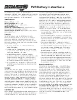
Figure 4-3 Description of the startup screen (two live wires)
(1) Normal mode (The solid line indicates
normal mode. The dotted line indicates non-
normal mode.)
(2) Input voltage and frequency
(3) Working mode
a
(4) Load power
(5) Output voltage, current, and frequency
(6) Bypass mode (The solid line indicates
bypass mode. The dotted line indicates non-
bypass mode.)
(7) Battery voltage and capacity displayed
during charge; Battery discharge time and
capacity displayed during discharge.
(8) Battery mode (The solid line indicates
battery in charge or discharge mode. The
dotted line indicates non-battery mode.)
NO TE
● UPS2000-G-15KRTL-01/UPS2000-G-20KRTL-01 If multiple working modes coexist, the
priority is as follows: converter mode (CM) > ECO mode > self-load mode (SM) >
normal mode (NM).
● a: indicates that only the UPS2000-G-15KRTL-01/UPS2000-G-20KRTL-01 is supported.
describes the icons on the menu screen.
Table 4-4 Icons on the screen
Icon
Meaning
Icon
Meaning
Mains input
Rectifier/Power
factor correction
(PFC) working
Inverter working
Bypass mode
Load power
Battery charging
UPS2000-G- (6 kVA-20 kVA)
User Manual
4 Control Panel
Issue 18 (2021-07-16)
Copyright © Huawei Technologies Co., Ltd.
46