6-58
6.5 Faults - No on-screen indications
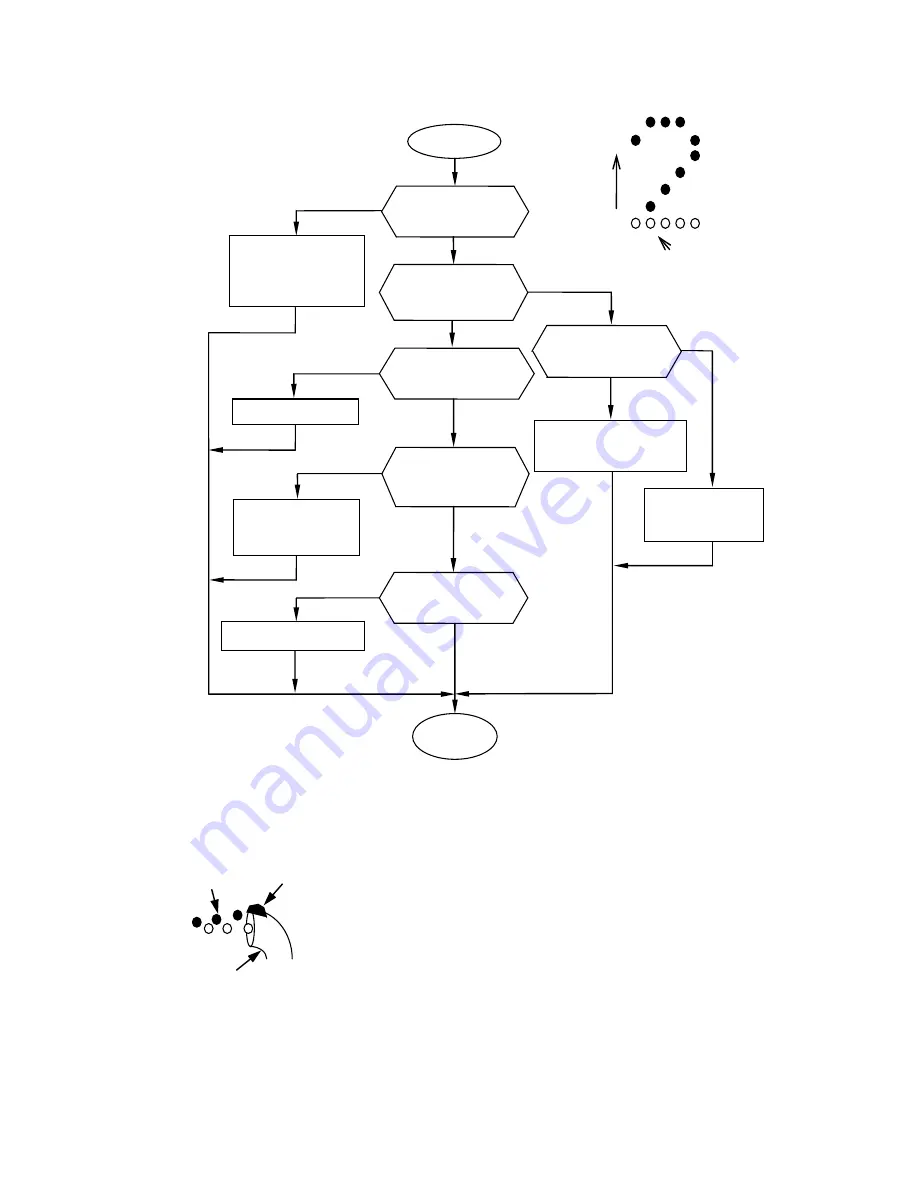
6.5.1 Chipped print (lower dots)
CAUTION
1.
If the ink stream is not centered with respect to the gutter,
dots having a small amount of deflection (lower dots of
characters) may collide against the gutter and fail to jet out
of the nozzle head, thereby causing chipped prints.
Position the ink stream at the center of the gutter.
2.
If the ink pressure rises, the ink stream flow rate increases
to decrease the amount of deflection, causing dots having a
small amount of deflection to collide against the gutter and
producing chipped prints. Ensure that the ink pressure
setting is within the specified limits.
Direction of
deflection
Missing dots
Gutter
Ink/foreign
matter
Print
drop
Chipped print
Replace the ink.
Adjust the ink stream
position so that the ink
stream is centered with
respect to the gutter.
No
Is the ink stream
positioned at the
center of the gutter?
Yes
Is the ink pressure
higher that the
specified limit?
No
Yes
Has the operating
time exceeded the ink
shelf life?
No
Yes
Resume the
operation.
Pour the makeup
over the gutter edge
section to clean it.
Is there ink or dirt
buildup on top of the
gutter edge section?
Yes
No
Adjust the charge voltage.
Yes
Is the charge
voltage properly
adjusted?
No
Adjust the ink
pressure until it is
within the limits.
Can the ink pressure be
adjusted?
No
Yes
Provide pressure relief,
then replace the
pressure-reducing valve.
Summary of Contents for IJ UX
Page 1: ...Service Manual HITACHI Printer Model UX Revision July 1 2015 Version ...
Page 2: ... Revision of UX service manual Revision Chapter Revised Page Frist Edition ...
Page 15: ...1 9 2 External views Rear side 1 2 2 Main body internal Appearance with inner cover T removed ...
Page 16: ...1 10 1 2 3 Print head UX E UX D B Air exhaust port ...
Page 107: ...3 27 Circuit diagram of EZJ127A ...
Page 108: ...3 28 Circuit diagram of EZJ127B ...
Page 122: ...3 42 Circuit diagram of EZJ129 ...
Page 131: ...3 51 3 3 20 Electrical Connection Diagram ...
Page 132: ...3 52 ...
Page 188: ...4 55 5 Reset the time of the R air filter to 0 on the Parts usage time management screen ...
Page 301: ...7 Attached Drawing 7 1 Circulation System Diagram Circulation System Diagram UX B D 7 1 ...
Page 302: ...Circulation System Diagram UX E 7 2 ...
Page 305: ...7 5 7 2 2 Electrical Connection Diagram UX B Basic model Electrical Connection Diagram UX B ...
Page 308: ... Nozzle diameter 65μm 7 8 7 4 Dimensions around charge electrode and deflection electrode ...


