background image

         GR SG9015831000000000

Preset Plus Feeder

confidential

C.1.56

16.3 Changing the separator roll position

The control system adjusts the separator roll position
according to the stock thickness. The separator rolls
can swing to two different positions:

D

Paper mode: Up to a stock thickness of
0.4 mm, the separator rolls remain in paper po-
sition.

D

Cardboard mode: If the stock is thicker than
0.4 mm, the separator rolls swing to the card-
board position after the first print sheet has
been fed in. 

For stock thickness values between 0.3 mm and
0.4 mm you may select paper mode or cardboard
mode. We recommend cardboard mode to print very
stiff material in this thickness range.

Paper mode cannot be selected if the stock thick-
ness exceeds 0.4 mm.

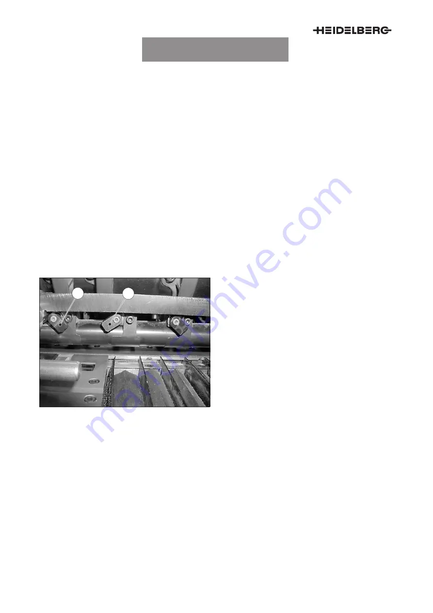
16.4 Throwing on/off individual separator rolls

1

2

Fig. 70

Throwing on/off separator rolls

You may throw off individual separator rolls. This can
be helpful for printing envelopes, for example, or
other materials of different thickness.

Throwing off the separator roll

1.

Fold the lever on the separator roll clockwise to
O.S. (Fig. 70/2).

Throwing on the separator roll

1.

Fold the lever on the separator roll anti-clock-
wise to D.S. (Fig. 70/1).

16.5 Cleaning the separator rolls

1.

Using a brush or compressed air, remove the
paper dust daily. 

2.

If a separator roll marks on the print sheet: 
Clean the separator roll with a lightly damp-
ened
 cloth. Use only water and the cleaners
that are approved by Heidelberg.

The separator roll must be replaced by Heidelberg
Service if it is still tight after it has been cleaned.

Summary of Contents for Speedmaster CD 102

Page 1: ...t is required for working safely on the press The main chapter B describes the function of the electric controller The main chapter C describes the mechanical com ponents of the Preset Plus feeder and...

Page 2: ...as software control and measuring devices of our machines are internationally protected by copy right patents and other intellectual property laws and regulations Any form of disclosure or reproductio...

Page 3: ...1 12 5 Suction head C 1 16 6 Overview table suction head settings for different printing materials C 1 22 7 Sheet separator fingers C 1 25 8 Adjusting blast air on the suction head C 1 27 9 Pile stops...

Page 4: ...printing unit SM 102 CD 102 with Preset Plus feeder D 2 8 Maintenance D 3 1 1 Feeder To be observed for all work D 3 3 2 Service activities on the preloading device D 3 4 3 Service activities on the s...

Page 5: ...ting the protective devices A 1 2 2 2 Symbols of the protective devices A 1 3 3 Protective devices on the Preset Plus feeder A 1 4 3 1 Fixed guards A 1 4 3 2 Moveable guards A 1 4 3 3 Guards on the Pr...

Page 6: ...Main chapter overview A 2...

Page 7: ...out working safely with the press D Before you start up the Preset Plus feeder read this operating manual and the operating manual you have received together with the press D Make sure that all person...

Page 8: ...ncy stop buttons 1 Press the Malfunction button Fig 1 1 in the banner line The Malfunction menu appears 2 Press the Service button Fig 1 2 The Ser vice menu appears 3 Press the Safety button Fig 1 3 T...

Page 9: ...ialize the test 1 Press the Reset button Fig 1 5 The test is initialized so that it can be repeated completely after an interruption for example 2 2 Symbols of the protective devices Fig 2 Feeder prot...

Page 10: ...are mounted on the press 3 2 Moveable guards The moveable electrically interlocked guards can be opened by hand to carry out makeready and maintenance work When you open an electrically protected gua...

Page 11: ...Fig Moveable guards Inching mode with travel limitation Inching mode without travel limitation Crawl speed mode 1 Glass sliding guard in front of the feeder pile noise protection Yes Yes Yes 2 Door on...

Page 12: ...the blowing suction nozzle 3 Propelling roller Increases the suction air volume of the propel ling roller 4 button Reduces the suction air volume of the propel ling roller 5 Pull plate Increases the s...

Page 13: ...e compressor Note The Halt button is not an Emergency stop button 13 Increase print speed Increases the press speed continuously 14 Reduce printing speed Reduces the press speed continuously 15 Inch f...

Page 14: ...n but tons Fig 7 25 and 26 are pressed at the same time 27 Increase lateral sheet separation blower sheet size Moves the opposite lateral sheet separation blower away from the pile The lateral sheet s...

Page 15: ...de with the pile when it is moved down Lower the pile before you move the suction head downwards 34 Height adjustment automatic ON OFF Selects the height adjustment operating mode The LED is ON Automa...

Page 16: ...es upwards as long as the button is pressed 4 Main pile down Moves the main pile down The downward movement stops approximately 12 cm above the ground Pressing the button again briefly moves the pile...

Page 17: ...blast air volume of the sheet sepa ration blowers 7 Lifting sucker distance Adjusts the magnitude of the stroke movement 8 Forwarding sucker D S Adjusts the level of the forwarding sucker D S 9 Suctio...

Page 18: ...the corner blow ers O S 3 Diagonal blower bars D S Adjusts the blast air volume of the diagonal blower bars D S 4 Diagonal blower bars O S Adjusts the blast air volume of the diagonal blower bars O S...

Page 19: ...he cover guide height later B 1 6 1 6 Adjusting the front lay deflection B 1 7 1 7 Switching automatic pull lay cleaning on off B 1 8 1 8 Switching the double sheet detector in the pull lay on or off...

Page 20: ...Main chapter overview B 2...

Page 21: ...b button Fig 1 1 in the banner line The Job menu appears 2 Press the Job preparation button Fig 1 2 The Job Job preparation menu opens 3 Press the Sheet travel button Fig 1 3 The Feeder Cover guide ai...

Page 22: ...er line 1 2 Sheet travel Feeder pile menu 5 0 mm Paper run Feeder pile 12345 Job Name 1 2 3 4 Fig 2 Sheet travel Feeder pile menu 1 Press the Sheet travel button Fig 2 1 in the banner line The Paper r...

Page 23: ...ed blast air Speed compensation ON The buttons and are used for adjusting the compensation value 0 100 Speed compensation OFF The buttons and are used for adjusting the blast air volume 20 100 5 Pile...

Page 24: ...appears above the bar chart 5 Use the and buttons Fig 4 5 to adjust the suction air at the propelling roller The se lected value appears above the bar chart 6 Use the and buttons Fig 4 6 to adjust th...

Page 25: ...exceeds 0 4 mm cardboard mode is selected automatically and can not be deselected afterwards Fig 5 4 1 Press the Sheet travel button Fig 5 1 in the banner line The Paper run menu appears 2 Press the...

Page 26: ...cover guide height later 1 Press the Sheet travel button Fig 6 1 in the banner line The Paper run menu appears 2 Press the Feeder button Fig 6 2 The Paper run Feeder menu appears 3 Press the Cover gui...

Page 27: ...t in order to adjust it to the cut edge of the printing material 1 Press the Sheet travel button Fig 7 1 in the banner line The Paper run menu appears 2 Press the Feeder button Fig 7 2 The Paper run F...

Page 28: ...r each washup of the blanket 1 In the header press the button Malfunction Fig 8 1 The Malfunction menu appears 2 Press the Service button Fig 8 2 The Ser vice menu appears 3 Press the Basic settings b...

Page 29: ...vice menu appears 3 Press the Basic settings button Fig 9 3 The menu Basic settings Start up warning signal appears 4 Press the Feeder button Fig 9 4 The Basic adjustments Feeder menu Fig 9 appears 5...

Page 30: ...ion It is not suitable for D Double layer printing materials such as enve lopes D Printing material of a grammage of more than 600 g m2 1 Press the Malfunction button Fig 10 1 The Malfunction menu app...

Page 31: ...trasonic double sheet de tector you may D switch on both double sheet detectors D switch off the double sheet detector in the pull lay or the ultrasonic double sheet detector One of the two double she...

Page 32: ...Pile height sensor is soiled 11 Pile height sensor is not initialized 11 3 Fig 11 Malfunctions in the pile height sensor Symbol Error message Type Pile height sensor defective Notify your authorized S...

Page 33: ...alfunction Feeder 12345 Job Name Entire press Peripheral units Ink control system Lubrication center 1 2 Bundle to forwarding roller 11 3 3 Fig 12 Bundle to forwarding roller Symbol Error message Type...

Page 34: ...12345 Job Name Entire press Peripheral units Ink control system Lubrication center 1 2 Mechanical DBK 11 3 3 Fig 13 Double sheets or multiple sheets on tear off detector Symbol Error message Art 3 Me...

Page 35: ...13 4 3 Method of operation in Automatic mode C 1 15 5 Suction head C 1 16 5 1 Components of the suction head C 1 16 5 2 Adjusting the format C 1 17 5 3 Adjusting the height C 1 17 5 4 Lifting suckers...

Page 36: ...omatic adjustment of the lateral sheet separation blowers C 1 35 11 3 Manual adjustment of the lateral sheet separation blowers C 1 36 11 4 Setting the blast air volume C 1 36 12 Rope guide C 1 37 12...

Page 37: ...Throwing on off individual separator rolls C 1 56 16 5 Cleaning the separator rolls C 1 56 16 6 Cleaning the sheet guide plate C 1 57 17 Front lays C 1 58 17 1 Function C 1 58 17 2 Throwing on off th...

Page 38: ...Main chapter overview C 4 20 Adjustment information for special printing material C 1 74 20 1 Special printing material C 1 74 20 2 Book paper C 1 74...

Page 39: ...o injuries of the fin gers Switch off the feeder and secure it against being switched on inadver tently before you start any adjustment work Warning Rotating rollers and cyl inders are crushing points...

Page 40: ...uction tape on the feed table Mechanical pull lay Mechanical pull lay Pneumatic pull lay The feeder components must be adjusted manually Once the format has been entered at the CP2000 Center the follo...

Page 41: ...ne of danger that nothing can be pinched under neath the pile support plate 2 Press again the Main pile down button The pile support plate D stops briefly above the ground D aligns itself automaticall...

Page 42: ...fter the alignment process has been completed If the feeder is not switched on you must manually raise the pile Note The governor foot Fig 1 1 on the suction head must be in inquiry posi tion Fig 1 6...

Page 43: ...ng members Fig 3 2 and the non stop bar Fig 3 1 are in a holding device Fig 3 on the feeder On D S there is a scale Fig 2 1 with a white and a black area D White area Fig 2 2 Changing piles is possibl...

Page 44: ...ched 3 Hook the non stop bar Fig 5 3 with the guide rail upwards to the retainer on D S and O S Fig 5 1 The non stop bar must lock home on D S and O S 4 Press the Auxiliary pile down button Fig 4 2 Th...

Page 45: ...r 9 Move the new pallet onto the pile support plate Center the pallet when you insert it 10 Move the pile Fig 6 1 upwards until it is approximately 10 cm below the auxiliary pile Fig 6 2 11 Use the Al...

Page 46: ...te Pile support plate and non stop bar can not collide If you do not raise the non stop bar manually it will be moved up wards as a function of the upwards motion of the pile support plate Feeder stop...

Page 47: ...dle stop Fig 10 1 in the center and to the cross bar on the floor Fig 10 2 6 Loosen the locking screws of the guide piece Fig 10 3 7 Push the guide piece Fig 10 4 to the stops 8 Close the lever 9 Push...

Page 48: ...in pile down button The pile support plate D stops briefly above the ground D aligns itself automatically in center posi tion D and continues its movement down to the ground 3 Move the empty pile carr...

Page 49: ...after the alignment process has been completed If the feeder is not switched on you must raise the pile manually Note The governor foot Fig 11 1 on the suction head must be in inquiry posi tion Fig 11...

Page 50: ...the sensors perform differ ent tasks Sensor on pull side The sensor Fig 12 1 measures the lateral distance between the pile and the lateral sheet separation blower Fig 12 2 It controls the pile such t...

Page 51: ...d pull distance during adjustment or when the buttons Fig 13 1 and Fig 13 4 are pressed at the same time Correcting the format moving the pile stops You can change the position of the lateral sheet se...

Page 52: ...main pile or auxiliary pile can be aligned with the buttons Fig 13 3 and Fig 13 6 These buttons do not have any function in Automatic mode The pile is aligned by the pile control system Pile to D S F...

Page 53: ...ed If the feeder has stopped Note The governor foot on the suction head must be in inquiry position 2 Press the Main pile up button until the pile stops The pile alignment system aligns the pile The s...

Page 54: ...rwarding sucker 5 Governor foot 6 Carrier air blowers 7 Sheet separation blower 8 Pile stop 9 Sheet separator finger 10 Inclination lifting sucker 11 Height lifting sucker 12 Blast air rear edge blowe...

Page 55: ...lision Ensure that the suction head does not collide with the pile or the pallet when you change the format setting manually 5 3 Adjusting the height 1 2 3 Fig 19 Adjusting the button format The heigh...

Page 56: ...de 1 Press the Front edge pile height control button Fig 19 3 until the LED in the button is ON The automatic front edge control mode is ac tive Automatic mode changing setpoint You can select a setpo...

Page 57: ...low the upper edge of the for warding flap Manual mode changing the height adjustment of the suction head Condition Automatic front edge control is switched off the LED in the button Fig 19 3 is OFF D...

Page 58: ...hout these special lifting suckers 3 Rotate the lifting sucker through 90 into the locking device Check the proper seating of the new lifting sucker 1 2 4 3 Fig 23 Adjusting the lifting sucker Adjusti...

Page 59: ...3 D the drop height of the forwarding suckers on D S via the lever Fig 24 4 The drop height of the forwarding suckers with respect to the sheet must be approximately 4 5 mm Reducing the suction air fo...

Page 60: ...ucker Suction disks Position Height Inclination A Nipples B Straight E 0 2 mm Slightly towards the rear edge F A Nipples B Straight E 0 2 mm Slightly towards the rear edge F A Gray C red D Straight E...

Page 61: ...200 g Cardboard 200 g Sheet separator fingers Inside Height Outside Height Slotted A 0 mm Brush A 0 mm Slotted A 0 mm Brush A 0 mm Normal B 0 mm Brush B A 0 mm Normal B 0 mm Brush B 0 mm Norm thick C...

Page 62: ...130 g Art printing lightweight cardboard 100 200 g Cardboard 200 g Rear sheet stops Position Distance Steel weight Plastic weight Outside 1 mm Top Bottom Outside 1 mm Top Bottom Outside 1 mm Top or bo...

Page 63: ...light printing materi als 2 Sheet separator fingers for medium heavy print ing materials 3 Sheet separator fingers for heavy printing mate rials The sheet separator fingers Fig 26 1 3 limit the fanni...

Page 64: ...4 Adjusting the distance to the pile Note Sheet separator fingers that protrude too far into the pile can obstruct the leaping up of sheets and lifting suck ers and thus trigger a missing sheet The pr...

Page 65: ...tion blower 7 Height lifting sucker 8 Height forwarding sucker D S 9 Suction head up 10 Suction head down 11 Blast air compensation increase blast air 12 Blast air compensation reduce blast air Adjust...

Page 66: ...a tion blowers Fig 31 1 on the control knob Fig 29 6 1 Fig 32 Sheet separation blowers adjusting the height Adjusting the height 1 Adjust the height of the sheet separation blow ers with the knurled n...

Page 67: ...of blast air The direction of the blast air of the outer carrier air blowers can be changed The direction of the blast air of the inner carrier air blowers cannot be changed 1 Loosen the 4 mm hexagon...

Page 68: ...34 2 on the rear edge blower 8 6 Pre separation air 2 4 1 3 5 6 Fig 35 Feeder air control control panel Adjusting the pre separation air The control knob Fig 35 6 on the feeder air control control pan...

Page 69: ...p The pile stops for the rear edge of the sheet sit on the suction head Fig 36 1 Components D Locking screw for sheet size adjustment Fig 37 1 D Locking screw swiveling the pile stop Fig 37 2 D Stop p...

Page 70: ...ht Fig 39 2 of the pile stop rest on the pile with their dead weight This setting is suitable for heavy papers and cardboard 1 2 Fig 39 Pile stop without steel weight Setting for thin printing materia...

Page 71: ...al The ionizing unit consists of D two ion blowers on the suction head D one ionizer in the delivery D and as an option one or two additional ion izer s in the feeder 10 2 Switching on 1 Switch on the...

Page 72: ...sheet width on D S and O S 3 Tighten the tommy bar screw Fig 41 1 Height 4 Use the knurled ring Fig 41 3 to adjust the height of the ion blower The center of the ion blower Fig 41 4 must be set to th...

Page 73: ...ower Fig 42 4 D and a diagonal blower bar Fig 42 3 The lateral sheet separation blowers must be ad justed such that they fan the upper sheets of the pile 11 2 Automatic adjustment of the lateral sheet...

Page 74: ...ot be changed 3 Open the wing screw Fig 42 1 on the diago nal blower bar 4 Adjust the diagonal blower bar Fig 42 3 to the sheet format 5 Close the wing screw Fig 42 1 on the diago nal blower bar 11 4...

Page 75: ...nected with a spring The spring ensures a constant rope tension Removing Slacken an intact rope before you remove it Installation Fasten the spring before you tighten the rope at the suction head If t...

Page 76: ...w Fig 50 1 on the suction head and remove the rope from the guide roll Fig 50 2 2 Using the control knob Fig 44 5 move the guide plate down 3 Loosen the five screws Fig 45 1 on the cover plate Fig 45...

Page 77: ...onfidential C 1 39 1 Fig 47 2 1 4 3 Fig 48 6 Detach the rope next to the lateral sheet sepa ration blower Fig 47 1 7 Remove the spring from the guide plate and detach the spring Fig 48 1 8 Remove the...

Page 78: ...ough the rope pulley and through the ear on the rope 10 Insert the spring lock into the groove on the pin 11 Hook in the spring and place the spring into the plate guide 12 Thread the rope through the...

Page 79: ...al C 1 41 1 2 Fig 51 1 2 1 1 Fig 52 15 Insert the cover plate Fig 52 2 and tighten the five screws Fig 52 1 on the cover plate 16 Remove the locking device from the borehole on the actuating bar Fig 5...

Page 80: ...at the same time is not possible 13 2 Ultrasound double sheet detector 1 Fig 53 The ultrasound double sheet detector protects the press against damages caused by infed double and multiple sheets The...

Page 81: ...rates an average value from the measured val ues of the most recent five sheets This average value is used as the reference value for the subse quent sheets Note Only use stock types as advance sheets...

Page 82: ...et and bundle multiple sheets is only possible if the stock thickness of a sheet is at least 0 4 mm Only bundles multiple sheets are detected if the stock thick ness is less than 0 4 mm Double sheets...

Page 83: ...Adjust the tear off detector multiple sheet detector at the control knob Fig 56 3 The control knob has a notch division of 1 100 mm Adjustment to paper thickness 1 Switch on feeder and sheet travel 2...

Page 84: ...the feeler roller Fig 57 onto the cross bar and push it to the required position 2 Secure the feeler roller on the cross bar with the knurled head screw Fig 57 1 Basic adjustment You must check the ba...

Page 85: ...1 Sheet travel is switched off The sheets on the feed table are transported to the printing unit in the direction of the sheet travel Ratchet pawl and sheet stop finger are closed 3 Remove the sheets...

Page 86: ...ioning the forwarding rollers Due to the bundle check there can be startup problems when you move the forwarding rollers on the sheets 1 Open the tommy bar screw Fig 60 1 2 Move the forwarding roller...

Page 87: ...ller for double sheet detection 3 Pull plate 4 Propelling roller 5 Retainer 6 Pull sensor 7 Pull sensor adjusting screw 15 3 Adjusting the sheet size Adjust pulling device and pull side via the CP2000...

Page 88: ...and propelling roller separately 1 Press D the button Fig 63 3 to increase the suc tion air volume on the pull plate D the button Fig 63 4 to reduce the suction air volume on the pull plate The curre...

Page 89: ...nction of the pulling de vice A signal sounds only during sheet travel if a sheet has not correctly been pulled to the stop of the pulling device A pull error is shown on the feeder display Fig 65 1 a...

Page 90: ...ror possible The sensitivity of the monitor increases if you reduce the number of notches you turn the screw Example One notch corresponds to 0 03 mm In basic adjustment a pull error is re ported if t...

Page 91: ...press can damage the equipment seri ously Ensure that screws or other small parts cannot get into the press 1 Loosen and remove the two screws Fig 67 4 on the guide block 2 Remove the guide block Fig...

Page 92: ...68 1 4 Align the retainer in parallel to the sheet stop 5 Install the guide block Fig 67 3 Secure the guide block with the two screws Fig 67 4 6 Adjust the retainer to the currently used printing mate...

Page 93: ...usting the height of the separator rolls To adjust the separator rolls use three strips of pa per of the current print job 1 Push the strips of paper between separator roll and feed table 2 Turn the k...

Page 94: ...Paper mode cannot be selected if the stock thick ness exceeds 0 4 mm 16 4 Throwing on off individual separator rolls 1 2 Fig 70 Throwing on off separator rolls You may throw off individual separator r...

Page 95: ...ate 1 Turn the screw Fig 71 1 back by one turn 2 Pull the sheet guide plate Fig 71 2 from D S out of the retainer 3 Clean the sheet guide plate with a lightly dampened cloth Use only water and the cle...

Page 96: ...his function is used for adjusting the gripper bite 17 2 Throwing on off the front lays 2 1 Fig 73 Throwing on off the front lays requires a 3 mm Allen key 1 Open the glass guard on the printing unit...

Page 97: ...osition when you start a new job This provides you with allowance in all directions D Do not change the adjustment of the front lays when you print on front and rear side in several press passes There...

Page 98: ...ion nozzles 1000 h 1 2 Fig 75 Air adjustment of the blowing suction nozzles The blowing suction nozzles Fig 74 1 guide the sheet under the cover guides 1 Adjust the blast air volume with the buttons o...

Page 99: ...for retain ing double sheets early sheets and late sheets on the feed table To perform certain adjustment work or to remove double sheets you can raise the sheet stop fingers 1 Press the Release shee...

Page 100: ...em and the printing unit The crash bar must be installed on the feed table and be adjusted to the cur rently relevant stock thickness 18 2 Adjusting the crash bar 1 2 Fig 78 Crash bar 1 Using the cont...

Page 101: ...nsole 2 The press must be non printing before work is started 3 Remove all sheets from the feed table 4 Fold up the feed table Fig 79 1 on O S 19 2 Removing the suction tape module 1 2 Fig 80 Removing...

Page 102: ...and remove the three screws under neath the crash bar on D S 4 Loosen and remove the three screws under neath the crash bar on O S 5 Lift the crash bar from the feeder and store it at a protected pla...

Page 103: ...the screws Fig 83 1 on D S and O S are acces sible 8 Loosen the screws Fig 83 1 on D S and on O S 9 Push the segments of the suction tape drive roller on D S and on O S outwards in the di rection of t...

Page 104: ...ape module 13 Four screws secure the suction tape module on the feeder frame Loosen the four screws Fig 87 1 Note The suction tape module is heavy Do not carry the suction tape module on your own Ask...

Page 105: ...Remove the guide plate Fig 89 2 from the suction tape module Fig 90 4 Turn the suction tape module over Fig 90 1 2 3 Fig 91 Removing the idler pulley Removing the rollers for the tape guide 5 Loosen t...

Page 106: ...Place the suction tape on the center of the suc tion tape module Ensure that the suction tape is underneath the guides of the suction tape module 1 2 Fig 94 Installing the idler pulley Installing the...

Page 107: ...the shaft idler pulley Securing the shafts 6 Tighten the two grub screws on the roller bear ings Fig 95 2 1 2 Fig 96 Guide plate on the suction tape Installing the guide plate 7 Place the guide plate...

Page 108: ...g in the suction tape Fig 98 4 and 5 are intended to help you with adjus ting the correct tape tension 2 Move the suction tape until D the first bore marking in the suction tape Fig 98 4 is at the lin...

Page 109: ...with a second person place the suc tion tape module onto the feeder frame Insert the suction tape module first at the suc tion tape drive roller then at the printing unit 3 Secure the suction tape mod...

Page 110: ...s of the suction tape drive roller on D S and on O S inwards in the direc tion of the arrow Fig 103 1 If necessary pull on the suction tape until the journals on the suction tape are flush with the gr...

Page 111: ...tear off detector multiple sheet de tector into operation 15 Fold the tear off detector multiple sheet detec tor Fig 106 2 into working position 1 Fig 107 16 Fold down the feed table Fig 107 1 on O S...

Page 112: ...ing this printing material you must chiefly take the porosity into account Suction head 1 Install the form B tissue paper suckers on the lifting suckers 2 Adjust the sucking level of the lifting sucke...

Page 113: ...suction tape as required Some book papers require a vacuum of 10 and less to be adjusted Prior to adjusting a vacuum of 25 2 Switch off the feeder 3 Open the bypass air flap on the suction tape On th...

Page 114: ...Preset Plus Feeder confidential C 1 76...

Page 115: ...nual lubrication with grease D 1 9 4 1 Types of lubricating points D 1 9 4 2 Lubricating devices D 1 9 4 3 How to apply lubricant D 1 9 5 Lubricants D 1 10 5 1 Approved lubricants D 1 10 6 Cleaners an...

Page 116: ...ork D 3 3 1 1 Safety instructions D 3 3 2 Service activities on the preloading device D 3 4 2 1 Preloading device D 3 4 3 Service activities on the suction head D 3 5 3 1 Suction head D 3 5 4 Service...

Page 117: ...erview D 3 7 1 Safety instructions D 3 18 8 Service activities on the sheet alignment system D 3 19 8 1 Air filter Suction air pull lay propelling roller D 3 19 8 2 Rotary valve suction tape vacuum re...

Page 118: ...Main chapter overview D 4...

Page 119: ...ion with grease D 1 9 4 1 Types of lubricating points D 1 9 4 2 Lubricating devices D 1 9 4 3 How to apply lubricant D 1 9 5 Lubricants D 1 10 5 1 Approved lubricants D 1 10 6 Cleaners and washing flu...

Page 120: ...Chapter overview D 1 2...

Page 121: ...ting press and the peripheral units at regular intervals For example the cooling air ducts of the main driving motor for powder dust and ink de posits Remove the deposits with dry blast air and a brus...

Page 122: ...ce activities that are to be carried out on the printing press and on the peripheral units The checklists include information on the following items D Part D Maintenance work location D Auxiliary mean...

Page 123: ...intenance work to be done on the peripheral units e g compressors cen tral air supply and accessories The optimum value preservation of the peripheral units is achieved by regular and thorough mainte...

Page 124: ...e work are marked in color Refer to Maintenance in terval for more detailed information The following key explains the symbols used in the maintenance schedule The symbols illustrate the maintenance w...

Page 125: ...ng of the lubri cating point I 150 000 impressions or daily red II 750 000 impressions or weekly yellow III 3 000 000 impressions or monthly blue IV 15 000 000 impressions or twice a year Green V 30 0...

Page 126: ...Tag 1 2 Fig 1 Menu Counter 1 Selecting the menu Counter 2 Display Total impression counter totalizer reading 3 3 Menu Entire press Paper run CPTronic user interface 1 2 4 3 Fig 2 Selecting the display...

Page 127: ...le The lubricating points are filled with the oil gun 4 2 Lubricating devices Fig 5 Lubricating devices 1 Oil can Used on open oil lubrication holes 2 Grease gun Used for recessed grease nipples and o...

Page 128: ...CLP 150 ISO viscosity class ac cording to DIN 51519 ISO VG 150 mineral oil Note Lubricant used ex factory Mobil MOBILGEAR 629 il Grease gun Grease according to DIN 51825 KP2K 20 mineral oil lithium s...

Page 129: ...ability Insurance As sociation demands that cleaners meet the following requirements D Benzene percentage 0 1 D Toluene xylene content 1 D Aromatics content C9 1 D Solutions free from chlorinated hydr...

Page 130: ...intensive cleaners e g plate cleaners phosphoric cleaners tartaric acids D cleaners containing chlorine e g sanitary cleaners D strong lyes e g concentrated soap cleaners D chlorinated fluoride hydro...

Page 131: ...leaning work After each manual cleaning all parts must be rubbed with a cloth moistened with water 6 5 Approved cleaners for manual cleaning work Never splash cleaners containing ace tone and alcohol...

Page 132: ...efined cylinder jacket X X with Per fectJacket X X1 Plate cylinder blanket cylin der X X Inking rollers with rubber sleeve X X X3 Inking rollers without rub ber sleeve X X Dampening with rubber sleeve...

Page 133: ...er volume of up to 1 000 liters Part number 00 580 3902 D Aqua Clean AC5 100 tablets 1 tablet of Aqua Clean AC5 is sufficient for a water volume of up to 5 liters Part number 00 580 6353 D Aqua Clean...

Page 134: ...General information confidential D 1 16...

Page 135: ...ox D 2 4 2 1 Maintenance work has been performed D 2 4 3 Checklist for the Preset Plus feeder SM 102 CD 102 D 2 5 3 1 Service activities on the Preset Plus feeder D 2 5 4 Checklist for the printing un...

Page 136: ...Chapter overview D 2 2...

Page 137: ...hapter More precise descriptions of the individual mainte nance tasks on the peripheral units can be found in the corresponding operating manuals of the device manufacturers Please note The checklists...

Page 138: ...Checklists confidential D 2 4 2 Check list signature box 2 1 Maintenance work has been performed By On Maintenance interval Totalizer reading Signature UTK009040073000000000...

Page 139: ...ool Spare part re i d Maintenance interval K quired I II III IV V 1 Maintenance points on the preloading device Stop bar Clean the stop bars D S O S Cloth X X X 2 Maintenance points on the side stops...

Page 140: ...e lifting sucker guide Check the smooth functioning of the reinstalled lifting suck ers Note Do not lubricate Clean fluf fless cloth Brush X X X Check the state of the suction disks for wear and poros...

Page 141: ...cation Part No 8 Compressed air control unit Check the compressed air control unit for condensation water and drain it off if neces sary O S X X X X Check the system pressure on the manometer 6 4 0 3...

Page 142: ...uired I II III IV V 1 Maintenance points on the pull lays Reflex light button Clean the reflex light barrier D S O S Clean fluf fless cloth note the Ap proved clean ers list X X X X X 2 Maintenance po...

Page 143: ...enance points on the feed drum Gripper shaft bearing Lubricating 7 recessed grease nipples Grease gun Optimol Long ti PD 2 X X X Cam lever Lubricate 1 recessed grease nipple O S g time PD 2 X X X 8 Ma...

Page 144: ...Cleaning the rubber lip and blade trough Note the Ap proved clean ers list X X X 13 Collecting trough under the drop tubes of the inking roller washup de vice Check and if necessary drain the cleaner...

Page 145: ...on pile guide rail and pile transport D 3 11 5 1 Pile alignment D 3 11 5 2 Side stops D 3 12 5 3 Guide rail of the pile support plate D 3 13 5 4 Capacitive sensor Automatic pile transport changeover D...

Page 146: ...Chapter overview D 3 2...

Page 147: ...motion is possible while guards are open there is a risk of in jury in instances of improper operation When maintenance points on the feeder are involved pay attention to moving parts and to sheet in...

Page 148: ...nstalled in the feeder on D S and on O S 2 1 1 Cleaning the stop bars Maintenance point description Maintenance inter val 3 000 000 prints or monthly Maintenance loca tion D S O S Accessibility of lub...

Page 149: ...ifting suckers Cleaning and checking 2 3 1 Fig 3 Lifting sucker 1 Plate spring 2 Lifting sucker guide 3 Lifting sucker Note Do not lubricate Maintenance point description Maintenance inter val 3 000 0...

Page 150: ...f the installed lifting suckers 3 1 2 Checking the suction discs and replacing them if necessary 1 2 Fig 4 Suction discs of the lifting suckers 1 Lifting sucker 2 Suction disc Maintenance point descri...

Page 151: ...D S O S Accessing the main tenance point See installation and removal Maintenance work Clean 5 forwarding suckers Tool Soft fluffless cloth Cleaning solution See Approved cleaners Tab 4 Installing and...

Page 152: ...work Clean valve ports surface and bearing Tool Soft fluffless cloth brush Cleaning solution See Approved cleaners Tab 5 Caution Damage During any work on the rotary valve you must ensuring that the...

Page 153: ...sed air control unit 1 Manometer 2 Glass cylinder 3 Drain plug Caution The glass cylinder of the compressed air control unit Fig 9 1 must never be filled completely with condensation wa ter The conden...

Page 154: ...from the glass cylinder Never drain the glass cylinder in production or sheet travel mode 1 Open the drain plug until a spray of condensa tion water emerges 2 Close the drain plug once the glass cylin...

Page 155: ...1 1 Cleaning the adjusting spindles 1 2 Fig 11 Maintenance points on the spindles 1 Adjusting spindle 2 Adjusting spindle non stop only Maintenance point description Maintenance inter val 3 000 000 p...

Page 156: ...the side stop 1 2 Fig 13 Lubricating points on the bearing block of the side stops 1 Bearing block 2 Recessed grease nipple Lubricating point description Maintenance inter val 15 000 000 prints or tw...

Page 157: ...limit switch 1 2 Fig 15 Checking the function of the limit switches 1 Guide rail 2 Limit switch Maintenance point description Maintenance inter val 15 000 000 prints or twice a year Maintenance loca...

Page 158: ...is installed at the end of the feed table before the pile 5 4 1 Cleaning the capacitive sensor 1 Fig 17 Clean the sensor 1 Capacitive sensor Automatic pile transport changeover Maintenance point desc...

Page 159: ...ction tape reference 1 Reference 2 Mark suction tape 3 Mark feed table 4 Suction tape Maintenance point description Maintenance inter val 3 000 000 prints or monthly Maintenance loca tion Center Acces...

Page 160: ...e Fig 19 4 2 Check at the tolerance adjustment range Fig 20 4 whether the mark suction tape Fig 20 2 is between the marks feed table Fig 20 3 3 If necessary adjust the suction tape tension or replace...

Page 161: ...feed table re lease 2 pipe clamps Number type main tenance work Clean the air filters carefully knock out or vacuum Tool Vacuum cleaner Lubricant Tab 12 6 2 2 Replacing the air filter suction tape su...

Page 162: ...risk of in jury in instances of improper operation When you clean the cylinders make sure that the ball of your hand points in the direction of the infeed nip and the fingers in the direction of the o...

Page 163: ...ing roller is installed underneath the feed table 8 1 1 Cleaning the filter cartridge 1 Fig 25 Cleaning the filter cartridges suction air pull lay propelling roller 1 Filter cartridge suction air pull...

Page 164: ...ations or yearly Maintenance loca tion D S middle Accessing the main tenance point Open the feeder guard fold up the feed table open the service port Number type main tenance work Replace 2 air filter...

Page 165: ...alve surface 2 Valve ports 3 Cover plate 4 Bearing Note Do not lubricate Maintenance point description Maintenance inter val 3 000 000 press rotations or monthly Maintenance loca tion Center Accessing...

Page 166: ...Maintenance confidential D 3 22...

Page 167: ...ce Menu Counter display Total impression counter D 1 8 CPTronic user interface Menu Entire press Paper run D 1 8 Crash bar Adjusting C 1 62 Function C 1 62 D Double sheet detector Bundle detector B 1...

Page 168: ...Maintenance reduces costs D 1 3 Maintenance interval 15 000 000 impressions or twice a year green D 1 7 150 000 impressions or daily red D 1 7 3 000 000 impressions or monthly blue D 1 7 30 000 000 i...

Page 169: ...reset Plus feeder SM 102 CD102 D 2 5 Printing unit with Preset Plus feeder SM 102 CD 102 D 2 8 Service instructions D 1 3 Sheet separation blower Adjusting the blast air C 1 28 Sheet separation blower...

Page 170: ...Index E 4 V VISCOGEN KL 300 Lubricant of the central grease lubrication D 1 10 W Washing fluid D 1 14...

Reviews: