Appendix 4. Nomographs
291
Appendi
x
=
(
)
t
T
T
Vy
T
t
T
T
t
T
T
T
Vy
Vy
−
+
−
⎪⎭
⎪
⎬
⎫
⎪⎩
⎪
⎨
⎧
⎟⎟
⎠
⎞
⎜⎜
⎝
⎛
−
×
−
⎟⎟
⎠
⎞
⎜⎜
⎝
⎛
−
×
−
−
2
1
2
2
2
2
1
2
1
2
1
1
2
exp
exp
…………
(
6
)
A4.2 Radius Direction Error at Circle Cutting
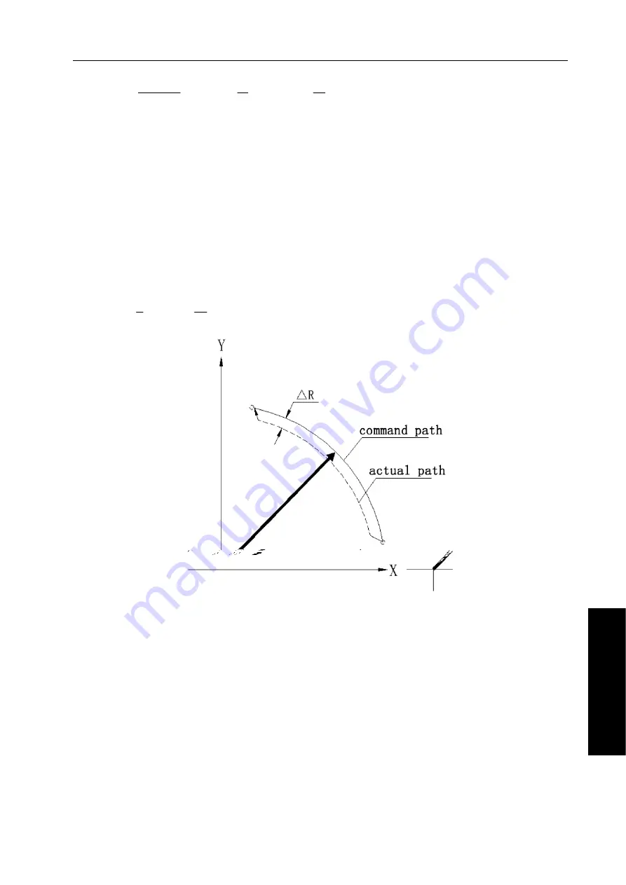
When a DC servo motor is used, the positioning system will produce a delay between input axis
and output axis. Since the tool advances along the specified segment, an error is not produced in
linear interpolation. In circular interpolation, however, radial errors may be produced, especially for
circular cutting at high speeds. This error can be obtained as follows:
R: maximum radius error
△
(
mm
)
V: feedrate
(
mm/s
)
r: circle radius
(
mm
)
T
1
: exponential acceleration/deceleration time constant
(
s
)
during cutting
(
T
1
= 0
)
T
2
: time constant of positioning system
(
s
)(
inverse of position loop gain
)
△
r =
(
)
r
V
T
T
2
2
2
2
1
2
1
×
+
………………………………………………
(
1
)
Since the machining radius r (mm) and allowable error r (mm) of the workpiece is given in
△
actual machining, the allowable limit feedrate V (mm/s) is determined by equation (1).
Since the acceleration/deceleration time constant during cutting which is set by this equipment
varies with the machine tools, please refer to the manual issued by the machine tool builder.
Summary of Contents for GSK983Ma
Page 124: ......
Page 143: ......
Page 185: ......
Page 209: ...Chapter Four Operation 197 Part 2 Operation ...
Page 239: ...Chapter Four Operation 227 Part 2 Operation ...
Page 242: ......
Page 279: ......
Page 296: ...GSK983Ma Milling Machine Center CNC System User Manual 284 Part 2 Operation ...
Page 371: ...Appendix 11 USB Interface Parameter Transfer Operation ...


