


Chapter 4 Machine Debugging
179
Inst
allation
and
Ⅳ
connection
L1
L2
L3
Use a servo motor with a mast (set the position parameter NO.6#6=1
,
A/B type block. Logic before and after the block
are the same
):
When the system executes the machine zero return, the machine slide moves to the set zero return direction, and its
distance is L1, and its speed is the value set by P100-104, and its acceleration/deceleration time constant is set by the
data parameter P352(Common for all axes). When the zero return switch responses the zero return block, the zero
return deceleration signal G17.0-G17.4 are valid. When the system decelerates to the speed set by P342-P346, and the
acceleration/deceleration time constant is set by P353(Common for all axes). When the inductive switch leaves the zero
return block, the system immediately decelerates to the speed set by P99 to wait the one-rotation signal
(
nPC
)
. After
receiving nPC signal, the system stops, and takes the point (D) as the machine zero. The zero return is completed.
Note
:
1. Regulate the parameters P100-104 and P352 to ensure stable start/stop at L1 block.
2. Regulate the parameters P100-104 and P353 to ensure the system does not cause vibration at L1
decelerating to L2 (point B), and ensure to decelerate to the speed set by P342-P346 at L2 block.
3. Regulate the parameters P342-P346 to ensure the system does not cause vibration at L2
decelerating to L3 (point C).
4. To get zero return precision, L3 should be less than 2MM.
5. When the system sets zero return before block, the system decelerates to 0 at L2 and then
reversely moves at the speed set by the data parameter P342-P346.
6. Using the grid offset function (only for L3'
抯
s movement direction offset), set the data parameter
P180-183 to the required offset distance (L4
,
Unit: MM
)
. When the system executes zero
return, point E is taken as the machine zero.
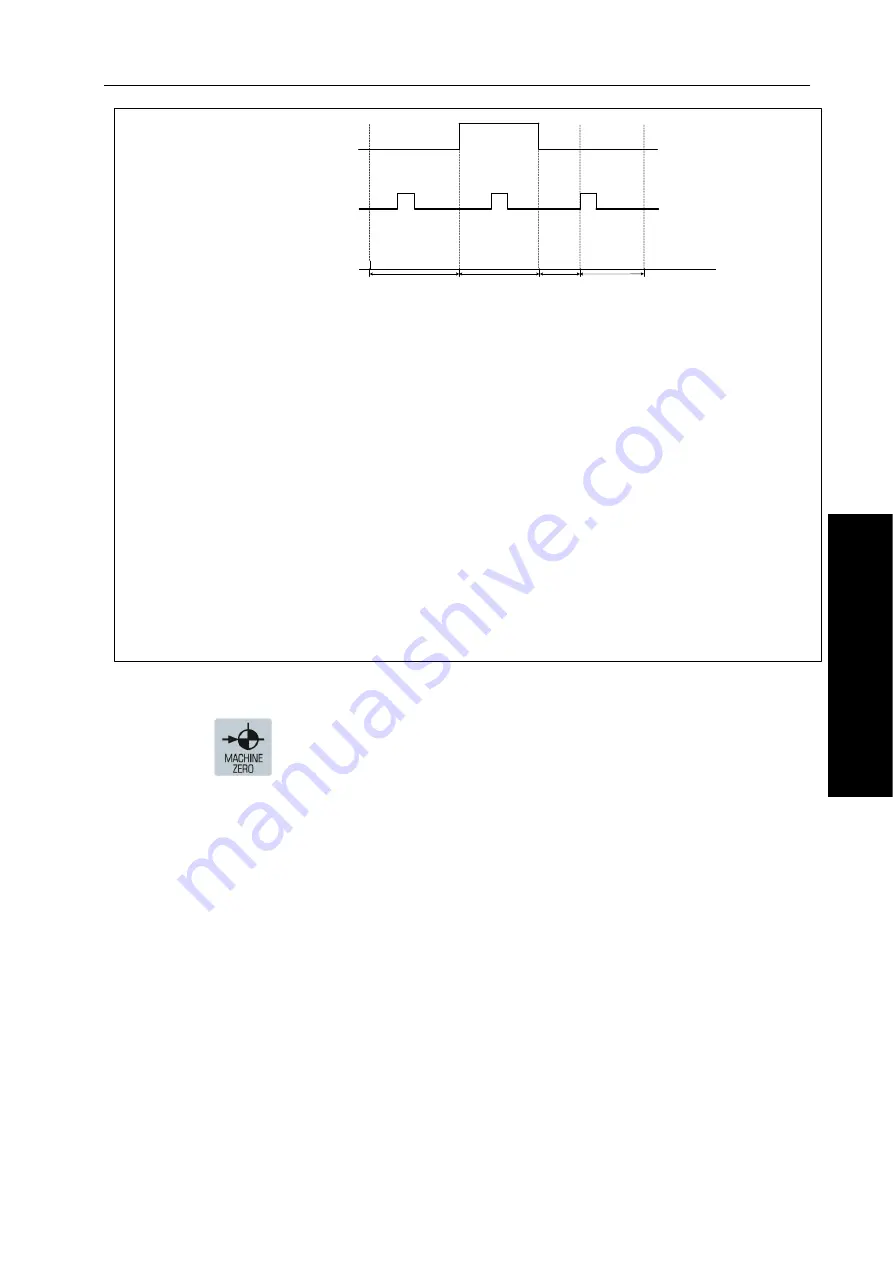
Signal time sequence diagram with a mask servo motor: A/B type zero return mode
Zero return deceleration signal
DEC
(
G196.0-G196.4
)
Mask?one-rotation signal nPC
Zero return start
A
B
C
D
E
L4
Machine
zero
Fig. 4-8-1-1
Operation steps of bus incremental servo’s mechanical zero return:
(
1
)
Press
to enter the mechanical zero return mode, and then “mechanical zero return”
is displayed at the bottom right corner on LED screen.
(
2
)
Select X, Y, 4
TH
or 5TH axis for mechanical zero return, and zero return direction is set by bit
parameters N0:7#3
~
N0:7#4.
(
3
)
The machine moves along the mechanical zero point, before the deceleration point, the
machine traverses rapidly, and the traverse speed is set by the data parameters
P100
~
P104
.
After touching the deceleration switch, each axis returns to the mechanical zero point (the
reference point) at the speed set by P342~P346. After separating from the block, move the
machine zero at the speed FL (data parameter P099). During returning the mechanical zero point,
the coordinate axis stops moving, the zero return indicator is ON.
Example:
Taking an example of the 1st axis’ common incremental zero return, the 1st axis strikes the block
at the speed F4000
(
the data parameter P100 is set to 4000
),
it passes the block after encountering
the deceleration switch at F500
(
the data parameter P342 is set to 500
)
. After it leaves the block, the
1st axis searches one-rotation Z pulse signal at the speed F40
(
the data parameter P99 is set to 40
)
,
and it stops after it receives the signal, which is shown in Fig. 4-8-1-2.
Summary of Contents for 980TC3 Series
Page 13: ...1 Programming Ⅰ Programming Ⅰ ...
Page 71: ...59 Operation Ⅱ Ⅱ Operation ...
Page 97: ...85 III Ⅲ Function III Function ...
Page 149: ...137 Installation and Connection Ⅳ Ⅳ Installation and Connection ...
Page 209: ...197 附 录 Appendix ...


