


Chapter 4 Reference Point Return
95
Ⅲ
Function
Chapter 4 Reference Point Return
4.1
Manual Reference Point Return
General
In manual reference point return mode, the machine tool move in the specified direction
by setting the position parameter N0
:
7#0~#4 to execute the reference point return. The
selected axis on the panel reports the axis to execute the machine zero return, which is
not related to the move direction of axis.
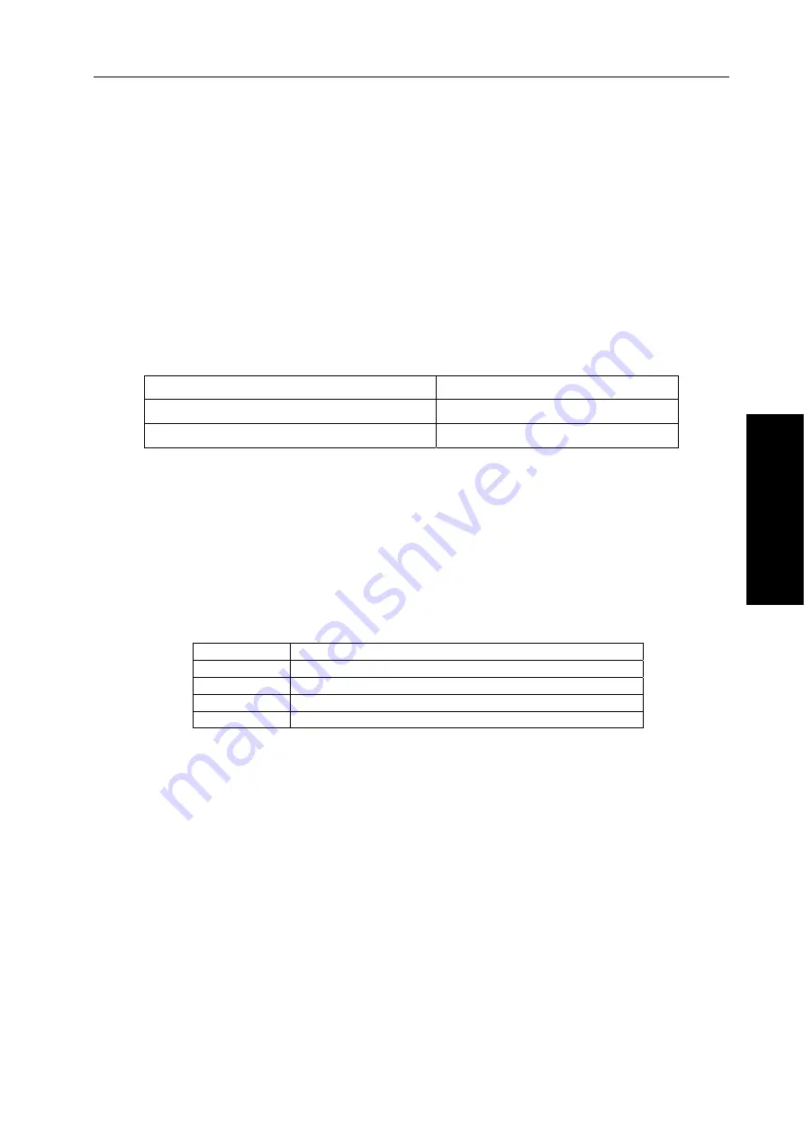
The following signals are related to the manual reference point return:
Table 4-1-1
Manual reference point return
Reference point return deceleration signal
DECX, DECY, DECZ,DEC4,DEC5
Reference point return completion signal
ZP1, ZP2, ZP3, ZP4, ZP5
Signal
Reference point return completion signals
ZP1
~
ZP5(F094
#
0~F094
#
4)
[
Classification
]
Output signal
[
Function
]
These signals report that the machine tool is at the reference point on a
controlled axis.
These signals correspond separately to all axes.
Table 4-1-2
ZP1 The
1
st
axis reference point return completion signal
ZP2 The
2
nd
axis reference point return completion signal
ZP3 The
3
rd
axis reference point return completion signal
ZP4 The
4
th
axis reference point return completion signal
ZP5 The
5
th
axis reference point return completion signal
[
Output conditions
]
When these signals becomes 1:
z
Manual reference point return is completed and the current position is
in the in-position area.
z
The automatic reference point return(G28) is completed and the
current position is in the in-position area.
z
The reference point return check is completed and the current position
is in the in-position area.
When the signal becomes 0:
z
The machine tool moves from the reference point.
z
The emergency stop signal appears.
z
The servo alarm appears.
Reference point return deceleration signal check
*DEC1~*DEC5 (G0196#0~G0196#4)
[
Classification
]
Input signal
[
Function
]
These signals decelerate the feedrate for manual reference point return to a low feedrate
in order to approach the reference point at the low feedrate.
Summary of Contents for 980TC3 Series
Page 13: ...1 Programming Ⅰ Programming Ⅰ ...
Page 71: ...59 Operation Ⅱ Ⅱ Operation ...
Page 97: ...85 III Ⅲ Function III Function ...
Page 149: ...137 Installation and Connection Ⅳ Ⅳ Installation and Connection ...
Page 209: ...197 附 录 Appendix ...


