


12-3
When It Does Not Work Right
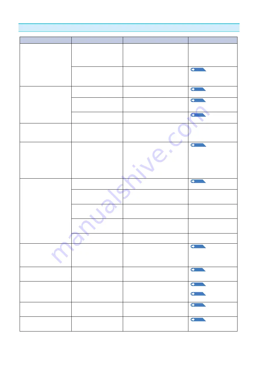
Symptom
Possible Cause
Solution
Reference
• Drops the meda whle
detectng.
Brght lght mght be shnng
onto the meda sensor.
Block the lght f there s drect sunlght
shnng on the plotter that s placed
near the wndow.
Move away the fluorescent lamps if
there s one close to the plotter.
Meda sensor may be
defectve.
Contact your sales representatve
or the Graphtec call center. Set the
meda sensor to DISABLED to use the
plotter temporarly.
P.9-4
Enablng/
Dsablng the Meda
Sensors (MEDIA SENSOR)
• Meda wobbles.
Push rollers are not set
correctly on the grt rollers.
Check the poston of the push rollers.
P.2-7
Loadng Meda
(Paper)
Changng of the hold-down
force of the push roller s not
sutable for the meda.
Please set a meda sutable for
changng the hold-down force.
P2-18
Changng the
Hold-down Force
Roll meda s not set properly.
Set the roll meda properly.
P.2-7
Loadng Meda
(Paper)
• One of the push roller goes
off the meda.
The leadng edge or the
tralng edge of the meda s
not cut straght aganst the
meda.
Cut the edge of the meda straght.
• A "Poston Error" appears
when the tool carrage hts
the left sde of the devce
after settng the meda and
choosng a meda type. Or
a "Poston Error" appears
when t hts the rght sde of
the devce.
Push roller sensor may be
defectve f t hts the left sde
of the plotter.
Home sensor may be
defectve f t hts the rght
sde of the plotter.
Contact your sales representatve or
the Graphtec call center. Set the push
roller sensor to DISABLED to use the
plotter temporarly.
P.9-5
Enablng/
Dsablng the Push Roller
Sensors (PUSH ROLLER
SENSOR)
• The plotter stops wth
"POSITION ALARM"
displayed during initialization
or cuttng.
CONDITION settng for the
meda s nvald.
Slow down the speed or lower the
FORCE.
P2-30
Settng the Tool
Condton
The pen carrage does not
move by httng somethng.
Move the object dsturbng the
operaton, and turn on the plotter after
turnng t off once.
External force s appled to
the pen carrage whle cuttng.
Move the object dsturbng the
operaton, and turn on the plotter after
turnng t off once.
Movement s dsturbed by the
meda chaff n the operaton
area.
Move the object dsturbng the
operaton, and turn on the plotter after
turnng t off once.
The plotter s defectve.
Contact your sales representatve or
the Graphtec call center.
• It s cuttng wth orgn pont
shftng to center of the
meda.
Data created wth lower left
orgn pont s receved when
the plotter s set wth center
orgn pont.
(Wth HP-GL command)
Reset the orgn pont to center on
the applcaton software, or reset the
orgn pont of the plotter to lower left.
P3-9
Settng Orgn
Pont When HP-GL s Set
• Meda jumps out to forward
sde.
Selected wrong type of the
meda.
Check the type of meda, "SHEET",
"ROLL-1 REAR SET", or "ROLL-2
REAR SET".
P2-26
Settng Feedng
Method
• Dsplays command error.
Data sent to the plotter s not
correct.
Check the data.
P12-6
Error Message n
GP-GL Command Mode
P12-7
Error Message n
HP-GL Command Mode
• It cannot cut above certan
length.
Length of the cut s exceedng
the length of the page set on
the plotter.
Press the [FAST] key and check the
cuttng area.
Match the settng for the page length.
P4-5
Settng Length of
the Page
• There are too many tool up
and down.
Settng for the tangental
mode s set to ON.
Turn OFF the settng for the tangental
mode unless you are cuttng thck
meda.
P6-3
Settng the
Tangental Mode


