


Overview
2–15
Flow Control Overview
Flow Control Parameters
(Refer to Fig. 2.9)
The following flow control parameters are entered from
either the User Interface or from digital input:
Setpoint Source
– Specifies the source of the
flow limit value as User Interface, network or analog
input (refer to page 8–18).
Analog Scaling
– If analog is the source of input,
the scaling for analog input must be set. The setting
is used to calculate the relationship between the
flow rate and a 4–20 mA input signal (refer to page
8–18).
Flow Rate Setpoint
– Sets the value for the
desired flow rate. Flow control monitors and cali-
brates flow rate based on this value and the other
parameters (refer to page 9–9 or 9–16).
Delay Time
– Sets the time that flow control waits
after the gun is triggered before starting to monitor
the flow rate. This allows time for the fluid to quickly
reach the setpoint and avoid unnecessary alarms or
corrections (refer to page 8–19).
Flow Control Low Limit
– This value is only used
with manual guns and is always entered from the
User Interface (refer to page 9–9). The flow control
stops making adjustment if the flow rate falls below
the difference of setpoint and the “Low Limit”
volume. The warning alarm output will be on when
the actual flow rate falls out of this tolerance for 5
seconds. This helps the system allow for periodic
partial triggering (feathering) of a hand gun without
adjusting the flow rate.
If the setpoint is changed, the low limit will change
accordingly.
Example –
If the setpoint is 500 cc/min. and the low
limit is 100 cc/min.:
The flow control will stop making adjustments
when the flow rate falls below 400 cc/min.
Changing the setpoint to 300 cc/min. will
change the low limit value to 200 cc/min.
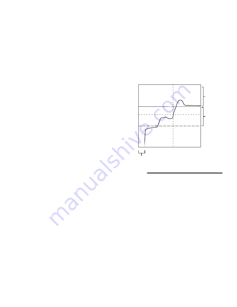
Delay Time
Time
Flow
Low Limit
Alarm
Tolerance
Flow Rate Setpoint
Fig. 2.9
Gun “feathered”,
No Flow Control
Full Flow Control
NOTE: Graph shown for hand gun flow control.
Alarm
Tolerance
Summary of Contents for PrecisionMix ii
Page 6: ...6 ...
Page 7: ...1 1 Warnings Warnings 1 ...
Page 8: ...1 2 Warnings ...
Page 11: ...Overview 2 1 Overview 2 ...
Page 12: ...2 2 Overview ...
Page 15: ...Overview 2 5 ...
Page 31: ...Installation 3 1 Installation 3 ...
Page 32: ...Installation 3 2 ...
Page 58: ...Installation 3 28 Notes ...
Page 67: ...Operation 4 1 Operation 4 ...
Page 68: ...Operation 4 2 ...
Page 83: ...Operation 4 17 Notes ...
Page 90: ...Operation 4 24 ...
Page 91: ...Screen Map 5 1 Screen Map 5 ...
Page 92: ...5 2 Screen Map ...
Page 94: ...5 4 Screen Map ...
Page 95: ...Run Monitor 6 1 Run Monitor 6 ...
Page 96: ...Run Monitor 6 2 ...
Page 103: ...Totalizers 7 1 Totalizers 7 ...
Page 104: ...Totalizers 7 2 ...
Page 108: ...Totalizers 7 6 ...
Page 109: ...System Configuration 8 1 System Configuration 8 ...
Page 110: ...System Configuration 8 2 ...
Page 142: ...System Configuration 8 34 ...
Page 143: ...Recipe Setup 9 1 Recipe Setup 9 ...
Page 144: ...Recipe Setup 9 2 ...
Page 165: ...10 1 Troubleshooting Troubleshooting 10 ...
Page 166: ...10 2 Troubleshooting ...
Page 182: ...10 18 Troubleshooting ...
Page 183: ...11 1 Service Service 11 ...
Page 184: ...11 2 Service ...
Page 192: ...11 10 Service ...
Page 193: ...12 1 Parts Parts 12 ...
Page 194: ...12 2 Parts ...
Page 207: ...12 15 Parts Notes ...
Page 228: ...12 36 Parts ...
Page 229: ...13 1 Utilities Software Utilities Software 13 ...
Page 230: ...13 2 Utilities Software ...
Page 254: ...13 26 Utilities Software ...
Page 255: ...14 1 Technical Data Technical Data 14 ...
Page 256: ...14 2 Technical Data ...
Page 259: ...14 5 Technical Data Notes ...


