Installation
3–20
System Installation
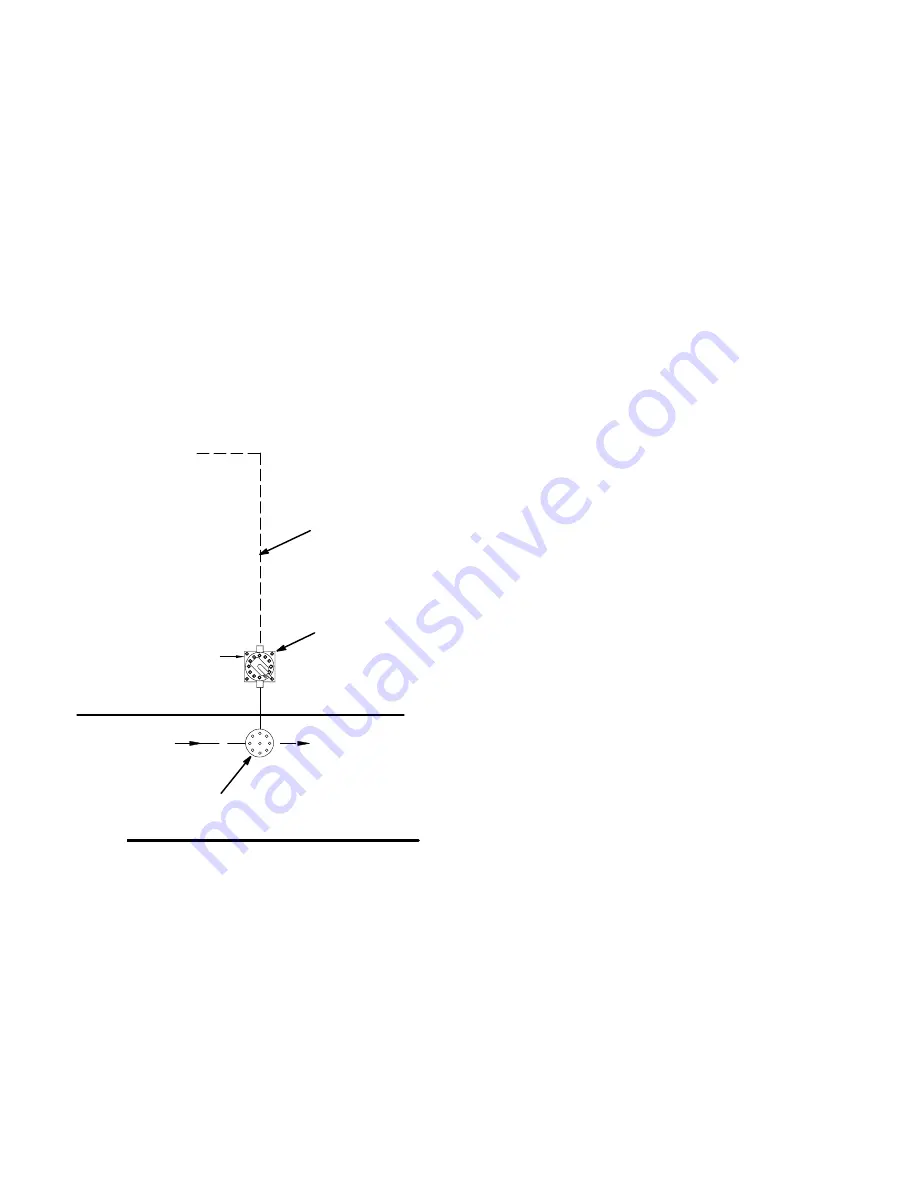
Install the Optional Flow Control
NOTE:
Refer to the system electrical schematic,
Manual 309138, included with the system.
1.
See Fig. 3.20. Install the fluid regulator (K) in the
spray booth, on the fluid supply line to the spray
gun. Locate the fluid regulator as close to the
spray gun as possible.
2.
Install the I/P transducer (F) in the non-hazardous
area, but as close to the fluid regulator as possible.
Mount the transducer on a vibration free surface.
100 ft. (30.5 m) of cable (C12) is supplied, con-
necting the I/P transducer to the controller.
3.
Connect a minimum 3/8 in. (10 mm) air supply line
to the I/P transducer (F).
4.
The I/P transducer supply air must be a maximum
of 100 psi (0.7 MPa, 7 bar), free of oil or water,
and filtered to a minimum of 40 micron.
9004A
Air in
Air out
Fluid in
C12
K
F
To Controller
Fluid out
Non-Hazardous Area
Hazardous Area
Fig. 3.20
Fluid Connections
Figs. 3.1 and 3.2.
1.
Connect the solvent supply line to the solvent inlet
on the fluid panel. If your system has color
change, make solvent connections to the color
change stack and the catalyst change stack.
2.
Connect the resin supply line, catalyst supply line,
and reducer supply line to their respective inputs
on the fluid panel. The fluid supplies must have
consistent, non-fluctuating pressure through the
full flow rate range.
3.
Connect a fluid hose between the spray gun and
the mixer outlet.
4.
Connect an atomizing air hose from the air flow
switch to the spray gun.
Pressure Test and Solvent Flush the
System
Before operating the system, perform the
Pressure
Test and Solvent Flush
procedures on page 3–36.
See system assembly drawings on electrical schemat-
ic 309138 for more specific details.
Summary of Contents for PrecisionMix ii
Page 6: ...6 ...
Page 7: ...1 1 Warnings Warnings 1 ...
Page 8: ...1 2 Warnings ...
Page 11: ...Overview 2 1 Overview 2 ...
Page 12: ...2 2 Overview ...
Page 15: ...Overview 2 5 ...
Page 31: ...Installation 3 1 Installation 3 ...
Page 32: ...Installation 3 2 ...
Page 58: ...Installation 3 28 Notes ...
Page 67: ...Operation 4 1 Operation 4 ...
Page 68: ...Operation 4 2 ...
Page 83: ...Operation 4 17 Notes ...
Page 90: ...Operation 4 24 ...
Page 91: ...Screen Map 5 1 Screen Map 5 ...
Page 92: ...5 2 Screen Map ...
Page 94: ...5 4 Screen Map ...
Page 95: ...Run Monitor 6 1 Run Monitor 6 ...
Page 96: ...Run Monitor 6 2 ...
Page 103: ...Totalizers 7 1 Totalizers 7 ...
Page 104: ...Totalizers 7 2 ...
Page 108: ...Totalizers 7 6 ...
Page 109: ...System Configuration 8 1 System Configuration 8 ...
Page 110: ...System Configuration 8 2 ...
Page 142: ...System Configuration 8 34 ...
Page 143: ...Recipe Setup 9 1 Recipe Setup 9 ...
Page 144: ...Recipe Setup 9 2 ...
Page 165: ...10 1 Troubleshooting Troubleshooting 10 ...
Page 166: ...10 2 Troubleshooting ...
Page 182: ...10 18 Troubleshooting ...
Page 183: ...11 1 Service Service 11 ...
Page 184: ...11 2 Service ...
Page 192: ...11 10 Service ...
Page 193: ...12 1 Parts Parts 12 ...
Page 194: ...12 2 Parts ...
Page 207: ...12 15 Parts Notes ...
Page 228: ...12 36 Parts ...
Page 229: ...13 1 Utilities Software Utilities Software 13 ...
Page 230: ...13 2 Utilities Software ...
Page 254: ...13 26 Utilities Software ...
Page 255: ...14 1 Technical Data Technical Data 14 ...
Page 256: ...14 2 Technical Data ...
Page 259: ...14 5 Technical Data Notes ...


