


Section 3 Display Symbology
3-12
IDU-450 EFIS Software Version 8.0H (Rotorcraft)
1
st
Ed Nov 2018
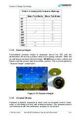
The airspeed box pointer interacts with the airspeed
scale and has graduations every five measurement units
with labels every 10 measurement units with high
numbers at the top. The airspeed scale range has at
least 40-75 measurement units. During an ADC failure,
a red “X” is displayed in place of the airspeed scale.
Figure 3-22: Airspeed Display
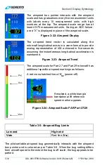
The airspeed trend vector is calculated along the
rotorcraft longitudinal axis is in a worm format to provide
analog representation of IAS achieved in five seconds
assuming the instantaneous longitudinal acceleration is
maintained.
Figure 3-23: Airspeed Trend
The airspeed scale for Part 27 and Part 29 rotorcraft has
additional specific airspeed markings as follows:
A red cross-hatched line at
V
NE
(power-off).
Figure 3-24: Airspeed Scale FAR Part 27/29
Table 3-5: Airspeed Bug Limits
Low end
High end
V
MIN
Red-line (
V
NE
)
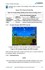
The pilot-settable airspeed bug geometrically interacts with the airspeed
box pointer and is colored as per Table 3-6. When the bug setting differs
from aircraft speed to the extent the bug is off scale, the bug appears to be
parked.
If enabled, a white triangle
translational lift reference
speed marker appears.