


Section 3 Display Symbology
3-52
IDU-450 EFIS Software Version 8.0H (Rotorcraft)
1
st
Ed Nov 2018
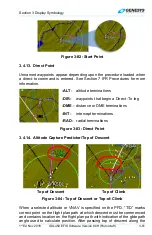
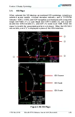
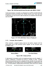
lubber line, altitude is captured and shown as a green arc located ahead of
the aircraft. The arc marks the bottom-of-descent or top-of-climb point.
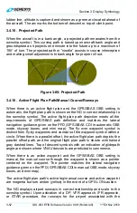
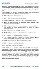
3.4.15. Projected Path
When the aircraft is in a bank angle, a projected path emanates from the
ownship symbol. This curving path is based upon aircraft bank angle and
groundspeed as it projects one minute into the future up to a maximum of
180° of turn. The projected path or “noodle” assists in course interception
and making small adjustments to bank angle for proper roll out.
Figure 3-85: Projected Path
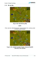
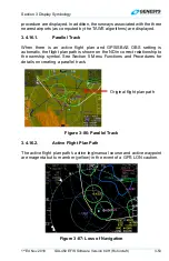
3.4.16. Active Flight Plan Path/Manual Course/Runways
When there is an active flight plan and the GPS/SBAS OBS setting is
automatic, the flight plan path is shown on the ND in correct relationship to
the ownship symbol. The active flight plan path depiction meets all the
requirements of GPS/SBAS path definition and matches the lateral
navigation guidance given on the PFD (GPS/SBAS CDI in automatic OBS
mode, skyway boxes, and mini map). The fly-over waypoint symbol is
distinct from fly-by waypoints and consists of the waypoint symbol within a
circle. When there is a parallel offset, the active flight plan path depicts the
parallel offset path, and the original flight plan path is shown with haloed
gray dashed lines. Top of descent symbols with an indication of glidepath
angle are shown where VNAV descents are predicted to commence.
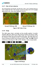
When there is an active waypoint and the GPS/SBAS OBS setting is
manual, the manual course through the waypoint is shown as a pointer
centered on the waypoint. The pointer matches the lateral navigation
guidance given on the PFD (GPS/SBAS CDI in manual OBS mode, skyway
boxes, and mini map).
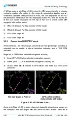
The active flight plan path’s active leg/manual course and active waypoint
are magenta but turn amber (yellow) in the event of a GPS LON caution.
The ND displays airport runways in correct relationship and scale to the
ownship symbol. Upon activation of a DP, VFR approach, IFR approach,
or STAR procedure, the runways for the airport associated with the