GE
V
OLUSON
i / V
OLUSON
e
D
IRECTION
KTI106052, R
EVISION
10
S
ERVICE
M
ANUAL
3-52
Section 3-5 - Connection of Auxiliary Devices
3-5-11
Connecting the Color Printer
3-5-11-1
Connection directly to the Voluson i / Voluson e system
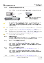
The Color Printer can be connected to the USB ports (
upper
or
lower
) on the rear connectors panel.
NOTE:
For installation instructions see:
Section 3-7-2 "Installing Digital Color Printer Sony UP-D23MD or UP-D25MD" on page 3-83
.
NOTE:
After physical connection of the printer to the Voluson i / Voluson e system: To assign a key to the Color
printer, follow the instructions in
Section 3-7-6 "Printer Remote Control Selection" on page 3-97
.
3-5-11-2
Connection via USB hub
As stated above. Safety considerations must be taken into account. The Color Printer must be powered
via an isolation transformer. An USB port may be used to communicate with the device.
3-5-11-3
Voluson i / Voluson e mounted on Modo Cart
NOTE:
For instructions see:
Section 3-5-1-3 "Mounting large Peripherals (e.g., Color Printer)" on page 3-28
.
The Color Printer may be connected to the USB ports on the rear of the Voluson i / Voluson e.
The Color Printer must be powered from the Modo Cart itself, via one of the isolated peripheral power
cables provided on the Modo Cart.
3-5-11-4
Voluson i / Voluson e mounted on Dock Cart
NOTE:
For instructions see:
Section 3-5-2-6 "Mounting large Peripherals (e.g., Color Printer)" on page 3-34
.
The Color Printer may be connected to the USB ports on the rear of the Voluson i / Voluson e.
The Color Printer must be powered from the Dock Cart itself, via one of the isolated peripheral power
cables provided on the Dock Cart.
3-5-11-5
Voluson i / Voluson e mounted on Voluson Station
NOTE:
For instructions see:
Section 3-5-3-9 "Mounting large Peripherals (e.g., VCR)" on page 3-42
.
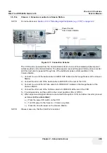
Figure 3-66 Connection Scheme - Color Printer
CAUTION
!! CAUTION:
When connecting the Color Printer directly to the system, it is necessary to use an additional power
source.
As a safety requirement, the Color Printer internal AC/DC must be medical grade
(conforming 60601-1 standard) or the safety must be ensured by the use of a medical grade
isolation transformer.
NOTICE
!! NOTICE:
The switch of the printer has to be in ON position before starting the system.
Leave printer switch always in the ON position.
power
socket
USB cable
NOTICE
:
Auxiliary equipment with direct mains
connection requires galvanic
separation e.g. by use of a medical
grade isolation transformer.
Summary of Contents for Voluson i BT06
Page 2: ......
Page 11: ...GE VOLUSON i VOLUSON e DIRECTION KTI106052 REVISION 10 SERVICE MANUAL ix ZH CN KO...
Page 44: ...GE VOLUSON i VOLUSON e DIRECTION KTI106052 REVISION 10 SERVICE MANUAL xlii Table of Contents...
Page 514: ...GE VOLUSON i VOLUSON e DIRECTION KTI106052 REVISION 10 SERVICE MANUAL IV Index...
Page 515: ......

