GE
V
OLUSON
i / V
OLUSON
e
D
IRECTION
KTI106052, R
EVISION
10
S
ERVICE
M
ANUAL
8-78
Section 8-20 - Replacement of the Voluson Station Components
8-20-17-5
Top Column Front Cover - Installation Procedure
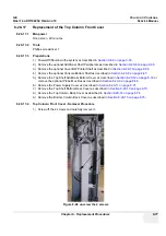
1.) Place the new Top Column Front Cover and fasten it with the 4 screws.
2.) Mount the Bottom Column Back Cover as described in
Section 8-20-15-5 on page 8-75
.
3.) Mount the Top Column Back Cover as descibed in
Section 8-20-14-5 on page 8-74
.
4.) Mount the Top Shelf Bottom Rear Cover as described in
Section 8-20-13-5 on page 8-73
.
5.) Mount the Power Supply Cover as described in
Section 8-20-11-5 on page 8-71
.
6.) Mount the Top Shelf Additional Bottom Cover as described in
Section 8-20-12-5 on page 8-72
or
mount the optional Probe Mux Box as described in
Section 8-20-9-5 on page 8-69
.
7.) Mount the optional Console Bottom Shelf as described in
Section 8-20-8-5 on page 8-67
.
8.) Mount the optional Cover BW Printer Shelf as described in
Section 8-20-7-5 on page 8-66
.
9.) Mount the optional Additional Shelf Peripherals as described in
Section 8-20-6-5 on page 8-65
Summary of Contents for Voluson i BT06
Page 2: ......
Page 11: ...GE VOLUSON i VOLUSON e DIRECTION KTI106052 REVISION 10 SERVICE MANUAL ix ZH CN KO...
Page 44: ...GE VOLUSON i VOLUSON e DIRECTION KTI106052 REVISION 10 SERVICE MANUAL xlii Table of Contents...
Page 514: ...GE VOLUSON i VOLUSON e DIRECTION KTI106052 REVISION 10 SERVICE MANUAL IV Index...
Page 515: ......


