GE
V
OLUSON
i / V
OLUSON
e
D
IRECTION
KTI106052, R
EVISION
10
S
ERVICE
M
ANUAL
Chapter 3 - Setup Instructions
3-43
3-5-4
Connecting the Wireless Network Adapter/Interface
3-5-4-1
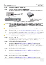
Connection directly to the Voluson i / Voluson e system
The Wireless Network adapter should be connected to the PCMCIA slot at the rear of the Voluson i /
Voluson e.
The Wireless Network Interface should be connected to the USB-Ports at the rear of the Voluson i /
Voluson e.
NOTE:
You only can use the Network Adapter
or
the the Network Interface.
1.) Power off/Shutdown the system as described in:
Section 3-6-3 on page 3-72
.
2.) Insert the Wireless Client Network adapter into the PCMCIA slot or the Wireless Network Interface
into the USB-Port at the rear of the Voluson i / Voluson e.
All software drivers are pre-installed for the designated Wireless Network adapter only.
3.) Turn ON the power of the system and wait till the system has booted.
NOTE:
After physical connection of the WLAN adapter/WLAN Interface to the Voluson i / Voluson e system,
follow the procedure described in
Section 3-11-1-7 "Wireless Network Configuration" on page 3-110
.
3-5-4-2
Voluson i / Voluson e mounted on Modo Cart
The Wireless Network adapter should be connected to the PCMCIA slot at the rear of the Voluson i /
Voluson e. Whenever moving the system with the Wireless Network adapter installed, make sure you
do not damage the adapter.
3-5-4-3
Voluson i / Voluson e mounted on Dock Cart
The Wireless Network adapter should be connected to the PCMCIA slot at the rear of the Voluson i /
Voluson e. Whenever moving the system with the Wireless Network adapter installed, make sure you
do not damage the adapter.
3-5-4-4
Voluson i / Voluson e mounted on Voluson Station
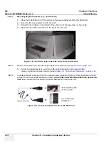
The Wireless Network adapter should be connected to the PCMCIA slot at the rear of the Voluson i /
Voluson e. Whenever moving the system with the Wireless Network adapter installed, make sure you
do not damage the adapter.
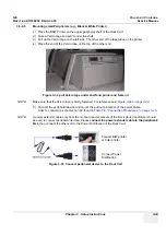
The Wireless Network Interface should be connected to the USB ports in the middle of the Voluson
Station.
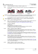
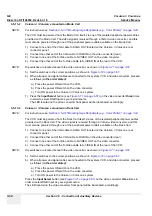
Figure 3-55 Connection Scheme - Wireless CardBus Network Adapter / Wireless Network Interface
This side up!
Eject button
PCMCIA slot
Summary of Contents for Voluson i BT06
Page 2: ......
Page 11: ...GE VOLUSON i VOLUSON e DIRECTION KTI106052 REVISION 10 SERVICE MANUAL ix ZH CN KO...
Page 44: ...GE VOLUSON i VOLUSON e DIRECTION KTI106052 REVISION 10 SERVICE MANUAL xlii Table of Contents...
Page 514: ...GE VOLUSON i VOLUSON e DIRECTION KTI106052 REVISION 10 SERVICE MANUAL IV Index...
Page 515: ......


