GE
V
OLUSON
i / V
OLUSON
e
D
IRECTION
KTI106052, R
EVISION
10
S
ERVICE
M
ANUAL
Chapter 8 - Replacement Procedures
8-33
8-14-4
Rigid Flex Assy - Removal Procedure
(cont’d)
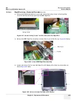
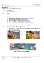
2.) Using a small slotted screwdriver or your nails, release the locking “noses” at the Rigid Flex
connector and then disconnect (pull out) the BBDI Rigid Flex.
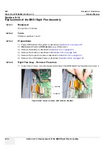
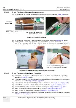
3.) Remove the BBDI Rigid Flex Assembly (inclusive Flex Cover and Ferrite; see:
Figure 8-42
below.
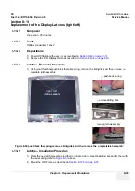
4.) Loosen and remove the 5 screws that fasten the LCD Display at the Rear Cover Assembly, as
shown
Figure 8-43
below.
Figure 8-41 release locking “noses” and then disconnect the Rigid Flex
Figure 8-42 remove BBDI Rigid Flex Assembly
Figure 8-43 remove 4 screws that fasten LCD Display
locking “noses”
Flex Cover
Ferrite
Summary of Contents for Voluson i BT06
Page 2: ......
Page 11: ...GE VOLUSON i VOLUSON e DIRECTION KTI106052 REVISION 10 SERVICE MANUAL ix ZH CN KO...
Page 44: ...GE VOLUSON i VOLUSON e DIRECTION KTI106052 REVISION 10 SERVICE MANUAL xlii Table of Contents...
Page 514: ...GE VOLUSON i VOLUSON e DIRECTION KTI106052 REVISION 10 SERVICE MANUAL IV Index...
Page 515: ......


