GE
V
OLUSON
i / V
OLUSON
e
D
IRECTION
KTI106052, R
EVISION
10
S
ERVICE
M
ANUAL
Chapter 8 - Replacement Procedures
8-71
8-20-11
Replacement of the Cover Bottom Voluson Station
8-20-11-1
Manpower
One person, 10 minutes
8-20-11-2
Tools
Phillips screwdriver 1
8-20-11-3
Preparations
none
8-20-11-4
Cover Bottom - Removal Procedure
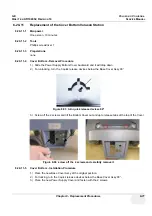
1.) Slide the Power Supply Bottom Cover backward and it will drop down.
2.) For unlocking, turn the 3 quick release devices below the Base Cover Assy 90°.
3.) Screw off the 2 screws and tilt the Bottom Cover out and up to release tabs at the top of the Cover.
8-20-11-5
Cover Bottom - Installation Procedure
1.) Place the new Base Cover Assy at the original position.
2.) For locking, turn the 3 quick release devices below the Base Cover Assy 90°.
3.) Place the new Power Supply Cover and fasten with the 2 screws.
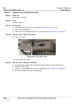
Figure 8-93 turn quick release devices 90°
Figure 8-94 screw off the 2 screws and carefully remove it
Summary of Contents for Voluson i BT06
Page 2: ......
Page 11: ...GE VOLUSON i VOLUSON e DIRECTION KTI106052 REVISION 10 SERVICE MANUAL ix ZH CN KO...
Page 44: ...GE VOLUSON i VOLUSON e DIRECTION KTI106052 REVISION 10 SERVICE MANUAL xlii Table of Contents...
Page 514: ...GE VOLUSON i VOLUSON e DIRECTION KTI106052 REVISION 10 SERVICE MANUAL IV Index...
Page 515: ......

