


___________________________________________________Chapter 6 – Testing and Repair, Page 6-29
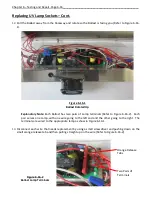
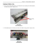
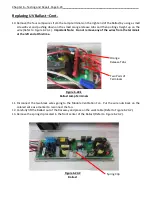
Replacing UV Ballast – Cont.
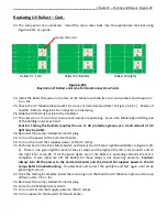
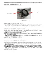
23.
The Lamp wires are numbered. Install the Lamp wires back into the appropriate terminal using
Figure 6-29-1
as a guide.
24.
Install the Ballast Raceway to the face of the Module with the five nuts and washers and torque to 7-
9 in – lbs.
25.
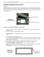
Check the UV Module Plate Gasket for cracks or deterioration (Refer to Figure 6-41-1). Replace if
needed. Refer to Page 6-41 for instruction on replacing.
26.
Slide the UV Module back into the Ventilator.
27.
The next step is to run a test to ensure all Lamps are operating. Secure the Module by installing one
of the holding nuts at each end.
Caution: Testing the Ballasts requires the use or UV protective glasses as a small amount of UV
light may be visible.
28.
Reconnect the Lamp / Ballast Connector plug.
29.
Turn on the power to the Command Center.
30.
Turn on the circuit that supplies power to the UV Lamps.
31.
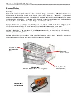
Push and hold in the Door Safety Switch and look at the UV Status Light Board (Refer to Figure 6-20-
2).
There is one green light for each of the six Lamps and the light on the left is for Lamp #1 and on
the right is for Lamp #6. If all the green lights are on the Ballast is operating correctly the test is
complete. If two lights are off, the Ballast for those lamps is not operating properly.
Caution:
Always turn off the power to the Command Center and the circuit that supplies power to the UV
Lamps
before troubleshooting.
Troubleshoot and correct the problem and test again until all six
green lights are on.
32.
Once the testing is complete install the remaining nuts that hold the UV Module in place and torque
all five nuts to 7-9 in - lbs.
33.
Reconnect the Lamp / Ballast Connector plug.
34.
Close the UV Module Access Doors.
35.
Turn on all circuits that supply power to the UV Lamps.
36.
Turn on power to the Gaylord Command Center.
1
3
5
7
9
11
2
4
6
8
10
12
Ballast #2 (Middle)
Ballast # 1 (Left)
Ballast #3 (Right)
Figure 6-29-1
Illustration of Ballast and Lamp Terminal Connections Points
Lamp Terminal


