


_____________________________________________Appendix B – Installation Requirements, Page B-3
Installation Requirements – Cont.
Ductwork
Grease exhaust ducts must be installed in compliance with NFPA-96, IMC and other applicable codes.
Use the following guidelines when installing the exhaust ducts:
1.
Exhaust ducts must be constructed of 16 gauge steel or 18 gauge stainless steel.
2.
Exhaust ducts must be constructed with continuous external welds and be grease and water tight.
3.
Exhaust duct must be continuously welded to the Ventilator duct collar.
4.
All elbows should be sweeping 90’s. Right angle turns or elbows less than sweeping may negatively
impact the performance of the Ventilator.
5.
All horizontal ducts should slope towards the Ventilator and/or towards an approved sump. Amount
of slope must be in accordance with the IMC or UMC.
Electrical
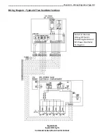
Refer to the wiring diagrams on the Gaylord Submittal Drawings for specific wiring interconnections.
1.
Command Center Electrical Power - Provide a 120 volt 20 amp service to the Gaylord Command
Center. Optional Voltage 220 volt 50/60 Hz.
2.
Wire the Command Center to the exhaust and supply fan(s).
3.
Control Wires - The Ventilator is supplied with a flex conduit with wires and ground extending 6 ft.
beyond one end of the Ventilator. Wire to the Command Center in accordance with the electrical
diagram.
4.
Multiple Section Control Wires - If the Ventilator is built in multiple sections, and if they contain
electric dampers, thermostats, or Autostart option, reconnect the flex conduit provided at the
section breaks. The electrical contractor is responsible for making these connections.
5.
Light Fixtures Electrical Power - If the Ventilator is provided with light fixtures, it is supplied with a
flex conduit with 2 wires and ground extending 6 ft. beyond the end of the Ventilator. Connect to a
switched lighting circuit as shown on the kitchen electrical plans. Ventilator may be equipped with
built-in light switch.
6.
Multiple Section Light Fixture Connection - Ventilators built in multiple sections have a flex conduit at
the section breaks for interconnecting the light fixture J-boxes. The electrical contractor is
responsible for making these connections.
7.
UV System Electrical Power – Each Ventilator section is supplied with a flex conduit with 2 wires and
ground extending 6 ft. beyond one end of the Ventilator. Wire to a separate 120 volt 20 amp service.
8.
UV System Control Wiring - The Ventilator is supplied with a flex conduit with wires and ground
extending 6 ft. beyond one end of the Ventilator. Wire to the Command Center in accordance with
the electrical diagram.
9.
Multiple Section UV System Control Wiring - Ventilators built in multiple sections have a flex conduit
at the section breaks for interconnecting the UV System control wiring. The electrical contractor is
responsible for making these connections.
10.
The UV Lamp Modules are shipped with the Ventilator in individual boxes. They are installed, and
tested by a Gaylord Certified Representative at the time of initial Start Up and Demonstration. Store
the UV Lamp Module boxes in a safe and secure area.
11.
Smoke Pollution Control (SPC) Wiring - The Ventilator is supplied with a flex conduit with wires and
ground extending 6 ft. beyond one end of the Ventilator. Wire to the Command Center in
accordance with the electrical diagram.
12.
Multiple Section SPC Wiring - Ventilators built in multiple sections have a flex conduit at the section
breaks for interconnecting the SPC system control wiring. The electrical contractor is responsible for
making these connections.


