


___________________________________________________Chapter 6 – Testing and Repair, Page 6-39
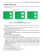
UV Ventilation Control Board – Cont.
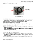
UV Monitoring Board
The UV Monitoring Board has several Status Lights advising of proper operation or of a fault (Refer to
Figure 6-38-1). The Status Lights indicate the following:
1.
Green light LED1 = On whenever there is power to the Ballast Contactor.
2.
Yellow light LED2 = On whenever a UV Lamp or Ballast has failed.
3.
Red light LED3 = On whenever one or more lights LED1 through LED6 are off.
4.
Green light LED5 = On whenever there is power to the UV Monitoring Board.
5.
Green Lights LED6 through LED10 on = UV Ventilation Control Board Operating Correctly.
6.
Green, Red and Yellow lights off = UV Ventilation Control Board Contactor failed, or the breaker
in the building electrical panel has tripped.
7.
Green light LED6 off and Red light on = Pressure switch open – low or no air flow through
ventilator.
8.
Green light LED7 off Red light on = First UV Module Access Door open.
9.
Green light LED8 off Red light on = High Temperature Shutdown Controller shut the system down
due to over 118° F. temperature in the Main Electrical Raceway.
10.
Green light LED9 off Red light on = Extractor Inspection Door open.
11.
Green light LED10 Red light on = Second UV Module Access Door open (if there is a second door).
12.
Yellow light on = UV Lamp or Ballast failure.
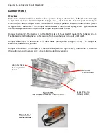
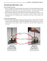
Status Light Relay
The relay troubleshoots the Ballast Contactor. If LED1 is off there is no power to the contactor. If there
is no power to the Ballast Contactor you can simulate power to the Ballast by flipping the Test Switch on
top of the relay (Refer to Figure 6-38-1).
Ballast Contactor
The Ballast Contactor moves to the closed position sending power to the UV Modules whenever the
Exhaust Fan is started and the Pressure Switch is closed (Airflow through the Ventilator), the UV Module
Access Doors are closed, the Extractor Inspection Doors are closed and the High Temperature Shutdown
Controller sensor has is below 118° F. If LED5, through LED10 are on and the Contactor will not engage it
indicates that the Ballast Contactor has failed.
If it is determined that any of these three components are defective the must be replaced.
Caution: Turn off all power to the Command Center and to the UV Ballast Box. There is a risk of shock,
injury, and /or death from live electrical components.


