


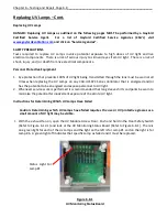


___________________________________________________Chapter 6 – Testing and Repair, Page 6-17
Replacing UV Lamp Sockets – Cont.
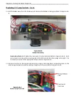
14.
Pull all the disconnected Lamp Sockets with wire from the Module.
15.
Each pulled wire has a wrapped number on each end. As an example the wire for Lamp #1 will have
one wire with the #1 on each end for the left end of the Lamp and one wire with the #7 on each end
for the right end of the Lamp (Refer to Figure 6-14-1 and 6-17-2).
The replacement Lamp Sockets
with wire come in a standard length, long enough to reach the furthest point. Using the old wire as a
guide cut the new wire the same length.
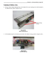
16.
Strip 1/4” off the end of the wire.
17.
Using number wraps, mark the wires at each end with the appropriate number.
18.
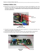
Insert all the wires through the appropriate ends of the Module and through the Module End Wire
Way that leads to the Ballast Raceway (Refer to Figure 6-17-1)
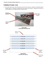
19.
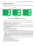
Using Figure 6-17-2
as a guide, rout all the wires over to the appropriate terminal.
20.
Using a small screwdriver push down on the small orange tab, insert the wire and release the tab.
(Refer to Figure 6-16-2).
1
3
5
7
9
11
2
4
6
8
10
12
Ballast #1 (Left)
Ballast #2 (Middle)
Ballast #3 (Right)
Figure 6-17-2
Illustration of Ballast and Lamp Terminal Connection Points
Lamp Terminals with Socket #.
Also Refer to Figure 6-16-2.
Figure 6-17-1
Module End Wire Way
Module End
Wire Way


