


___________________________________________________Chapter 6 – Testing and Repair, Page 6-43
Damper Motor – Cont.
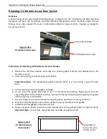
Replacing a Damper Motor
If it is determined that the Damper Motor has failed remove the old motor and install a new one as
follows.
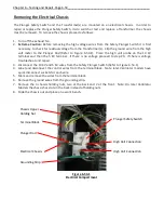
Removal
1.
Turn off the electrical power to the Command Center.
2.
Remove the Damper Motor Access Panel (Refer to Figure 6-42-1).
3.
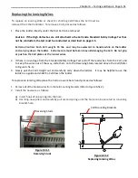
Loosen the two nuts on the Shaft Clamp (Refer to Figure 6-44-1).
4.
Remove the holding nut at the top of the motor.
5.
Slide the motor off the Damper Shaft and out of the Ventilator.
6.
Remove the cove from the j-box located behind the motor and disconnect the 3 wires from the
terminal strip.
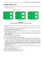
Replacing
1.
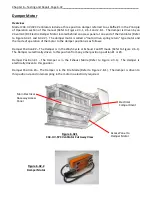
Next it is necessary to “set up” the motor prior to installing. Remove the “C” clip that holds the
Shaft Clamp and remove the Shaft Clamp (Refer to Figure 6-44-1).
Explanatory Note:
In examining the motor, note that it is two sided, with the plastic switches and
markings on one side being a mirror image of the other side.
The motor is always mounted vertical
with the electrical cord closest to the access panel (Refer to Figure 6-44-1).
Depending upon the type
of cooking equipment under the Ventilator and the number of Ventilator sections in a continuous
line determines which end of the Ventilator the Damper Motor is located. The location determines
which side of the Motor the Shaft Clamp is mounted on.
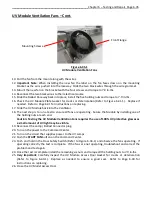
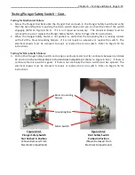
2.
With the Motor Crank provided, place the crank in the Crank Receiver (it does not matter which
side of the motor) turn the crank two full turns, and while holding the crank push the Spring Drive
Lock to the lock position then release the crank and then the lock (Refer to Figure 6-44-1).
3.
Looking at the end of the Motor with the electrical cord closest to you, place the Shaft Clamp on
the Shaft Receiver on the appropriate side, left side if the Motor is on the left end of the
Ventilator and right side if mounted on the right end, with the Shaft Clamp nuts facing you. In
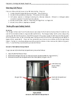
Figure 6-44-1 the Motor is set up for mounting at the left end. As a double check of facing the
Motor in the correct position, the arrow on the Crank Receiver should always be pointing
towards the back of the Ventilator (Refer to Figure 6-45-1).
4.
Slide in the “C” ring to lock the Shaft Clamp into position.
5.
Check to see that the End Switch Positioner Switch (not used for Gaylord application) is set to the
arrow that is in the same direction as the spring drive direction (Refer to Figure 6-45-2).
6.
Remove and throw away the Stop Screw located next to the Shaft Clamp (Refer to Figure 6-45-1).
This is not used on Gaylord applications.
7.
Of the 5 wires coming out the cord, only the Red, White and Black wires are used. Tape the Pink
and Orange wires back alongside the black cord. Connect the Red, White and Black wires to the
terminal strip.
Note:
All wires match color for color except the white wire from the Motor
connects to a light gray wire on the terminal strip. Replace the j-box cover.
8.
Slide the Motor over the Damper shaft and upper mounting stud, install the nut on the upper
mounting stud and torque to 7-9 in-lbs.


