


_____________________________________________________Chapter 6 –Testing and Repair, Page 6-1
Measuring Airflow
Overview
CG3-UVi-SPC Series Ventilators are factory engineered to operate at a specific exhaust volume, CFM
(Cubic Feet per Minute), based on, primarily, the type of cooking appliance, their associated energy
input, and the exact model of the Ventilator. Smoke capture, grease extraction efficiency and heat
removal are dependent upon the proper exhaust volume (Airflow) through the Ventilator. If the
exhaust volume is below design, smoke, grease and heat may escape the confines of the Ventilator
creating an uncomfortable kitchen for the operators. It will also reduce grease extraction efficiency
resulting in additional grease depositing in the duct system and exhaust fan. This can lead to sanitation
problems and fire hazards if left uncorrected. If the exhaust volume is higher than design, more energy
will be used to operate the exhaust fan, excessive noise levels may result, and grease can be pulled
through the extraction baffles and Particulate Separator depositing in the duct and fan. Operating the
Ventilator at higher or lower airflows than design will result in the entire kitchen ventilation system
being out of balance.
It is important that at initial installation of the Ventilator the exhaust volume is measured to verify that it
meets design. It is also recommended that the exhaust volume be measured once every two or three
years to insure that the exhaust fan is operating properly. The exhaust volume for each Ventilator
section is stamped on the Ventilator Nameplate (Refer to Appendix “A”
for a sample nameplate).
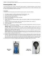
Measuring Airflow
The Ventilator exhaust volume may be determined by measuring the air inlet velocity, and using the Air
Velocity Chart, Chart C-6-4-1 and C-6-4-2,
determine the average exhaust volume in CFM Per Lineal Ft. of
Ventilator and comparing this average to the designed CFM/Lineal Ft. as noted on the Gaylord Submittal
Drawings. If the submittal drawing are not available, multiply the determined (as measured) CFM/Lineal
Ft. times the length of the Ventilator in feet, and compare this total to the total exhaust volume as
stamped on the Ventilator Nameplate.
The Air Velocity Chart gives the optimum inlet slot velocity and the minimum and maximum allowed
velocities. If the velocity is below or above the minimum or maximum, the exhaust fan must be adjusted
accordingly.
Important Note 1:
The height of the inlet slot can vary depending upon the design of the Ventilator. All
CG3-UVi Series Ventilators, except “DS” Series (Dual Slot), the nominal height of the inlet slot is either 3”
or 4”. In order to use the chart properly it is therefore important to first measure the inlet slot (Refer to
Chart C-6-4-1). On “DS” Series Ventilators the nominal height of the front inlet slot is always 3”. Use
Chart C-6-4-2 for all “DS” Series.
Important Note 2:
Some Ventilators may include Custom Air baffles to reduce the exhaust volume over
light duty cooking equipment (Refer to Figure 6-3-1 and 6-3-2). To determine if the Ventilator has
Custom Air baffles, refer to the Gaylord Submittal Drawings and the Custom Air baffles will be noted on
the front elevation. If not available, open the Extractor Inspection Door and look for the top Custom Air
baffle (Refer to Figure 6-3-1 and 6-3-2).


