


___________________________________________________Chapter 6 – Testing and Repair, Page 6-37
High Temperature Shutdown Controller – Cont.
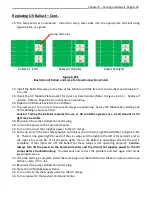
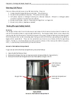
Checking the High Temperature Shutdown Controller Program
The High Temperature Shutdown comes programmed from the Gaylord factory and should never
need to be reprogrammed. To check the program, use the following instructions:
1.
Push the
START FAN
button on the Command Center. Check to insure that the Green UVi
System On status light is on.
2.
Confirm controller is showing current ambient temperature (Refer to Figure 6-36-1).
3.
Briefly push Set, “SP” will appear.
4.
Press set a second time, then release. “118” will appear. If it does not the control is
either faulty or needs to be reprogrammed. Consult a Gaylord Service Agency or call Gaylord
Industries for instructions.
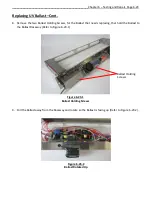
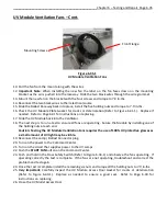
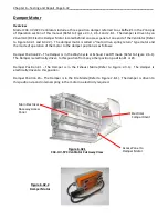
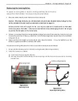
Safety Interlock Pressure Switch
Overview
There is a Pressure Switch mounted in the Main Electrical Raceway located above the UV Modules (Refer
to Figure 6-37-1).
The Pressure Switch monitors for negative pressure in the plenum of the Ventilator,
created when the exhaust fan is on. If the exhaust fan should malfunction, such as slipping or broken
belt, while the UV is on, the Pressure Switch will detect the reduction or absence of a negative pressure
and shut down the UV System. The Pressure Switch is factory set for 0.05” static and therefore does not
need adjustment.
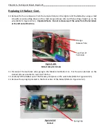
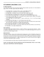
UV Ventilation Control Board
Overview
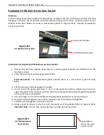
The UV Ventilation Control Board (Refer to Figure 6-38-1) monitors the Safety Interlock Pressure Switch,
the Extractor Inspection Doors Proximity Safety Switch and the UV Access Door Safety Switch. The UV
Ventilation Control Board is located behind the removable Main Electrical Raceway Access Panels (Refer
to Figure 6-38-2). When the exhaust fan is on and is operating properly, and both the Extractor
Inspection and UV Access Doors are closed, the Safety Interlock Pressure Switch sends a signal to
activate the Ballast Contactor allowing the UV System to operate. If the Safety Interlock Pressure Switch
detects low air flow, or if an Extractor Inspection Door or UV Module Access Door is open, a signal is sent
to deactivate the Ballast Contactor which turns off the UV System. The UV Ventilation Control Board has
three main components, the Ballast Contactor, the Status Light Relay and the UV Monitoring Board
(Refer to Figure 6-38-1).
Figure 6-37-1
Safety Interlock
Pressure Switch


