


Chapter 4 - Maintenance, Page 4-10________________________________________________________
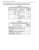
UV System Scheduled Preventive Maintenance – Cont.
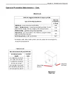
Preventive Maintenance
The following Preventive Maintenance items must be performed by a trained and qualified Certified
Service Agency at a frequency shown on page 4-8, Table T-4-8-1, EXHAUST SYSTEM INSPECTION
SCHEDULE. These tasks involve potential exposure to high doses of UV light and live electrical
components. There is a risk of shock, injury and/or death from contact with live electrical components.
1.
Testing UV Lamps and Ballasts
(For these tests all Extractor Inspection Doors, UV Module Access Door and ESP Cell Access Doors
must be closed and secured)
a)
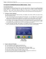
Turn on the exhaust fan at the Gaylord Command Center. The “UVi System On” green Status
Light in each Ventilator Section should be on. In addition to the Status Lights on the Ventilator,
the Gaylord Command Center displays text indicating the similar message as the Status Lights.
b)
If the yellow “UV Lamp Failure” Status Light is on it indicates that one or more of the UV Lamps
are not operating. To troubleshoot and replace a lamp refer to the Troubleshooting section page
5-8, and the Testing and Repair section of this manual beginning on page 6-7.
c)
If a Blue “UV System Standby” Status Light is on it indicates that one or more Extractor Inspection
Doors, UV Module Access Doors or ESP Cell Access doors have not been closed properly.
Figure 4-10-1
UV Status Lights
2.
Inspect and Clean UV Modules
a)
Turn off all power to the Gaylord Command Center.
b)
Turn off all circuits that supply power to the UV Lamps.
c)
For safety purposes turn off the cooking equipment and allow cooling.
d)
Cover any Deep Fat Fryers to avoid any matter from dropping into the fry pot.
e)
Open the UV Module Access Door (Refer to Figure 4-11-3).
f)
Disconnect the Lamp / Ballast Connector plug (Refer to Figure 4-11-1 and 4-11-2).
g)
Remove the eight nuts that hold the Module in place.


