


_____________________________________________________Chapter 6 –Testing and Repair, Page 6-3
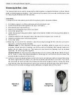
Measuring Airflow – Cont.
13.
The designed, or optimum velocity, is noted on the Submittal Drawings and on the Air Velocity Chart,
C-6-4-1. If the velocities are not within the ranges as shown on Chart C-6-4-1
and C-6-4-2
refer to the
Troubleshooting section of this manual for possible problems and corrective action.
If the velocities are within the range of the chart record the average velocity (FPM) on the Startup
Inspection Report and Test Report form. Note: two velocities will be recorded if the Ventilator
includes Custom Air Baffles. A sample report form, which can be photocopied, is provided in
Appendix
D.
14.
Repeat the process for any additional Ventilator sections.
Sensing Probe
Sensing Probe Guide
Bracket Gaylord Part
#
Optional Custom Air Baffles
Figure 6-3-1
Typical Section View
Top Edge of Inlet Slot
Optional Custom Air
Baffles
Figure 6-3-2
Typical Section View “DS” Series
Place Bottom of Sensing
Probe Even with Lower Lip
on Inlet Slot and Top of
Sensing Probe Against Back
Wall of Ventilator As Shown
Rear Slot Adjustable Baffle
Extractor Inspection Door
Extractor Inspection Door


