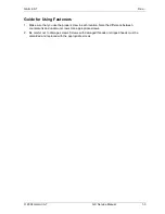
© 2004 Garmin AT
GX Service Manual
1-1
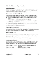
Chapter 1. Service Requirements
Preliminary Data
Prior to performing any repair or testing, fill out the appropriate fields of the Service Data Sheet. A
copy is located at the back of this manual. This will be used when service is completed to reenter
customer configuration and perform final test and inspection.
Service Authorization and Audits
Only UPS Aviation Technologies authorized Level II service centers can service UPS Aviation
Technologies avionics equipment. A level II service center must meet the following requirements:
•
FAA or local civil aviation authority repair station certification in the radio and/or navigation
category.
•
Completion of factory sponsored Level II training or passing a written test.
•
Possession of the most current version of the maintenance manual and/or applicable USP
Aviation Technologies service literature.
•
Fulfillment of the minimum test equipment requirements as listed in the maintenance manual,
including provisions for static control (ESD).
Contact UPS Aviation Technologies for more information.
Updating Service Manuals
It is required that all service centers have the latest revision of the service manuals prior to performing
any maintenance. The manual document numbers and configurations are available via the Internet or
by calling UPS Aviation Technologies at the numbers given in the front of this manual.
ESD Requirements
ESD precautions must be followed at all times when handling components or circuit boards. When
working on the unit, you must use a grounded wrist strap and a grounded working surface. Circuit
boards or components must only be carried in a nonconductive, anti-static bag. Reference EIA
Standard # EIA-625.
All components to be shipped require appropriate ESD protective packaging.
Soldering Requirements
Use a grounded tip, temperature controlled solder iron operating at 600 to 700 degrees Fahrenheit.
The solder, wick and flux are “no-clean” products. If others are used, the boards must be cleaned
after servicing to remove residues. See the parts list for these items. Reference the following
standards:
IPC-R-7721 and 7711 (or newer)
Guidelines for Rework and Repair of Printed Boards and
Assemblies.
IPC-A-610A (or newer)
Acceptability of Electronic Assemblies.
Summary of Contents for APOLLO GX SERIES
Page 8: ...Garmin AT Rev viii GX Service Manual 2004 Garmin AT This Page Intentionally Left Blank...
Page 12: ...Garmin AT Rev 1 4 GX Service Manual 2004 Garmin AT...
Page 24: ...Garmin AT Rev 2 12 GX Service Manual 2004 Garmin AT...
Page 26: ...Garmin AT Rev 3 2 GX Service Manual 2004 Garmin AT...
Page 27: ...2004 Garmin AT GX Service Manual 4 1 Chapter 4 Antenna Installation Guides...
Page 28: ...Garmin AT Rev 4 2 GX Service Manual 2004 Garmin AT...
Page 32: ...Garmin AT Rev 5 4 GX Service Manual 2004 Garmin AT...
Page 96: ...Garmin AT Rev 7 58 GX Service Manual 2004 Garmin AT...
Page 98: ...Garmin AT Rev 8 2 GX Service Manual 2004 Garmin AT Figure 8 1 GX55 Assembly Board Locations...
Page 122: ...Garmin AT Rev 8 26 GX Service Manual 2004 Garmin AT...
Page 130: ...Garmin AT Rev 9 8 GX Service Manual 2004 Garmin AT...
Page 140: ...Garmin AT Rev 10 10 GX Service Manual 2004 Garmin AT Figure 10 5 Comm Board Block Diagram...
Page 152: ...Garmin AT Rev 10 22 GX Service Manual 2004 Garmin AT...
Page 158: ...Garmin AT Rev 11 6 GX Service Manual 2004 Garmin AT...
Page 160: ...Garmin AT Rev 12 2 GX Service Manual 2004 Garmin AT...
Page 162: ...Garmin AT Rev 13 2 GX Service Manual 2004 Garmin AT...
Page 165: ......
Page 166: ......

