Garmin AT
Rev --
7-56
GX Service Manual
© 2004 Garmin AT
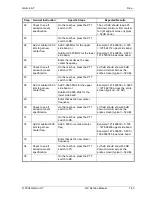
2. Press SEL to activate selection. The Mic 1 value will flash.
3. Turn the small knob to change the value.
4. Turn the large knob to the Mic 2 value. Turn the small knob to change the value.
5. Press ENTER to accept and save the settings.
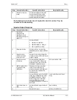
Receiver Squelch
Preset the receiver squelch level for values from 25-100.
1. In the Test Mode, rotate the large knob to select Receiver Squelch.
2. Press SEL to activate selection. The value will flash.
3. Turn the small knob to select a value.
4. Press ENTER to accept and save the settings.
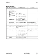
5. VHF Comm Checkout (GX60/65)
Receiver/Transmitter Operation
Tune the unit to a local frequency and verify the receiver output produces a clear and
understandable audio output. Verify the transmitter functions properly by contacting another
station and getting a report of reliable communications. Check the remote flip/flop.
Antenna Check
The antenna VSWR can be checked using an inline wattmeter in the antenna coax using
frequencies near both ends of the band. The VSWR should be < 2:1, and is not to exceed 3:1. A
VSWR of 2:1 will cause a drop in output power of approximately 12%, and 3:1 causes
approximately a 26% drop.
Sidetone Level Adjustment
The sidetone volume was preset at the factory to a typical audio level. The level can be adjusted
using one of the built-in system functions. To adjust the sidetone level:
1. Press SYS, rotate the large knob to the COM Info page, and press ENTER.
2. Rotate the large knob to the Sidetone Level page.
3. Press SEL, rotate the small knob to adjust the sidetone level, then press ENTER when
complete. The sidetone level is displayed in a range of 000 to 255, with 255 the highest level.
The sidetone level can be adjusted during transmit.
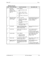
Comm Flight Test Check
A flight test is recommended as a final installation verification. The performance may be verified
by contacting a ground station at a range of at least 50nm while maintaining an appropriate
altitude and over all normal flight attitudes. Performance should be checked using low, high, and
mid band frequencies.
Summary of Contents for APOLLO GX SERIES
Page 8: ...Garmin AT Rev viii GX Service Manual 2004 Garmin AT This Page Intentionally Left Blank...
Page 12: ...Garmin AT Rev 1 4 GX Service Manual 2004 Garmin AT...
Page 24: ...Garmin AT Rev 2 12 GX Service Manual 2004 Garmin AT...
Page 26: ...Garmin AT Rev 3 2 GX Service Manual 2004 Garmin AT...
Page 27: ...2004 Garmin AT GX Service Manual 4 1 Chapter 4 Antenna Installation Guides...
Page 28: ...Garmin AT Rev 4 2 GX Service Manual 2004 Garmin AT...
Page 32: ...Garmin AT Rev 5 4 GX Service Manual 2004 Garmin AT...
Page 96: ...Garmin AT Rev 7 58 GX Service Manual 2004 Garmin AT...
Page 98: ...Garmin AT Rev 8 2 GX Service Manual 2004 Garmin AT Figure 8 1 GX55 Assembly Board Locations...
Page 122: ...Garmin AT Rev 8 26 GX Service Manual 2004 Garmin AT...
Page 130: ...Garmin AT Rev 9 8 GX Service Manual 2004 Garmin AT...
Page 140: ...Garmin AT Rev 10 10 GX Service Manual 2004 Garmin AT Figure 10 5 Comm Board Block Diagram...
Page 152: ...Garmin AT Rev 10 22 GX Service Manual 2004 Garmin AT...
Page 158: ...Garmin AT Rev 11 6 GX Service Manual 2004 Garmin AT...
Page 160: ...Garmin AT Rev 12 2 GX Service Manual 2004 Garmin AT...
Page 162: ...Garmin AT Rev 13 2 GX Service Manual 2004 Garmin AT...
Page 165: ......
Page 166: ......


