Garmin AT
Rev --
© 2004 Garmin AT
GX Service Manual
7-11
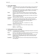
4. Annunciator Outputs
Description:
The GX50/60 includes six annunciator outputs intended for turning incandescent
lamps on/off. The six outputs are MSG, PTK, GPS, OBS/HLD, APPRCH, and
ACTIVE.
The GX55/65 includes two annunciator outputs intended for turning incandescent
lamps on/off. The two outputs are MSG and PTK. These are open collector
outputs capable of sinking 400 mA.
Setup:
If the TST-10 test station is not available, connect the annunciator outputs to
incandescent lamps, and the other side of the lamps to aircraft supply voltage
(Vac).
Operation:
Using the Lamp Outputs page in test mode, select on and off for each of the six
outputs by rotating the small knob.
Verification:
Verify that the lamps connected turn on and off as indicated on the GX display.
Alternate:
Connect the unit to nominal input supply voltage. Connect a 400 mA load
between each of the annunciator outputs and aircraft supply voltage (Vac). (If
Vac = 13.6 volts, then a load resistor of 33 ohms can be used.)
The load resistor is computed by:
(Vac - Vcesat) / Ioad = (13.6 volts - 1 volt) / 400 mA = 31.5 ohms.
(Rounding to 33 ohms is OK)
Verification:
Verify the output voltage of the six annunciator outputs as follows:
Lamp on: 1.0 VDC max
Lamp off: Vac ± 0.1 VDC min
5. Hold Input (Not present on GX55/65)
Description:
The waypoint sequencing hold input is a discrete input intended for connection to
a momentary button to aircraft ground.
Setup:
If the TST-10 test station is not available, connect the unit to nominal input supply
and connect a momentary switch from the Hold input to ground.
Operation:
Using the Lamp Outputs page in test mode, rotate the small knob to select the
Push WPT SEQ To Toggle OBS/HLD page. Press the Wpt Seq momentary
switch several times.
Verification:
Verify the OBS/HLD annunciator and the GX display change when pressing the
momentary switch.
Summary of Contents for APOLLO GX SERIES
Page 8: ...Garmin AT Rev viii GX Service Manual 2004 Garmin AT This Page Intentionally Left Blank...
Page 12: ...Garmin AT Rev 1 4 GX Service Manual 2004 Garmin AT...
Page 24: ...Garmin AT Rev 2 12 GX Service Manual 2004 Garmin AT...
Page 26: ...Garmin AT Rev 3 2 GX Service Manual 2004 Garmin AT...
Page 27: ...2004 Garmin AT GX Service Manual 4 1 Chapter 4 Antenna Installation Guides...
Page 28: ...Garmin AT Rev 4 2 GX Service Manual 2004 Garmin AT...
Page 32: ...Garmin AT Rev 5 4 GX Service Manual 2004 Garmin AT...
Page 96: ...Garmin AT Rev 7 58 GX Service Manual 2004 Garmin AT...
Page 98: ...Garmin AT Rev 8 2 GX Service Manual 2004 Garmin AT Figure 8 1 GX55 Assembly Board Locations...
Page 122: ...Garmin AT Rev 8 26 GX Service Manual 2004 Garmin AT...
Page 130: ...Garmin AT Rev 9 8 GX Service Manual 2004 Garmin AT...
Page 140: ...Garmin AT Rev 10 10 GX Service Manual 2004 Garmin AT Figure 10 5 Comm Board Block Diagram...
Page 152: ...Garmin AT Rev 10 22 GX Service Manual 2004 Garmin AT...
Page 158: ...Garmin AT Rev 11 6 GX Service Manual 2004 Garmin AT...
Page 160: ...Garmin AT Rev 12 2 GX Service Manual 2004 Garmin AT...
Page 162: ...Garmin AT Rev 13 2 GX Service Manual 2004 Garmin AT...
Page 165: ......
Page 166: ......


